Nissan Juke Service and Repair Manual : Evaporative emission system
Evaporative emission system: System Diagram
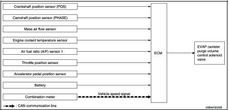
Evaporative emission system : System Description
INPUT/OUTPUT SIGNAL CHART
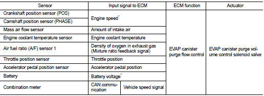
*: ECM determines the start signal status by the signals of engine speed and battery voltage.
SYSTEM DESCRIPTION
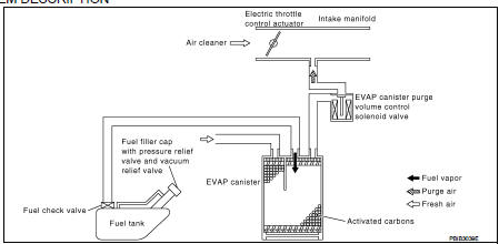
The evaporative emission system is used to reduce hydrocarbons emitted into the atmosphere from the fuel system. This reduction of hydrocarbons is accomplished by activated charcoals in the EVAP canister.
The fuel vapor in the sealed fuel tank is led into the EVAP canister which contains activated carbon and the vapor is stored there when the engine is not operating or when refueling to the fuel tank.
The vapor in the EVAP canister is purged by the air through the purge line to the intake manifold when the engine is operating. EVAP canister purge volume control solenoid valve is controlled by ECM. When the engine operates, the flow rate of vapor controlled by EVAP canister purge volume control solenoid valve is proportionally regulated as the air flow increases.
EVAP canister purge volume control solenoid valve also shuts off the vapor purge line during decelerating and idling.
 Starter motor drive control
Starter motor drive control : System Diagram
Starter motor drive control : System
DescriptionINPUT/OUTPUT SIGNAL CHART
INPUT/OUTPUT SIGNAL CHART
*: With Intelligent Key system
SYSTEM DESCRIPT ...
 Automatic speed control device (ASCD)
Automatic speed control device (ASCD)
: System Diagram
Automatic speed control device (ASCD)
: System Description
INPUT/OUTPUT SIGNAL CHART
*1: M/T models
*2: CVT models
BASIC ASCD SYSTEM
...
Other materials:
Periodic maintenance
REAR PROPELLER SHAFT
Inspection
APPEARANCE AND NOISE
• Check the propeller shaft tube surface for dents or cracks. If damaged,
replace propeller shaft assembly.
• If center bearing is noisy or damaged, replace propeller shaft assembly.
VIBRATION
If vibration is present at high speed, inspe ...
P1641 thermoplunger control unit
DTC Logic
DTC DETECTION LOGIC
Diagnosis Procedure
1.CHECK THERMOPLUNGER CONTROL UNIT POWER SUPPLY CIRCUIT
1. Turn ignition switch OFF.
2. Disconnect thermoplunger control unit harness connector.
3. Check the voltage between thermoplunger control unit harness connector and
ground.
Is the ...
IGN off interlock door unlock function does not operate
Diagnosis Procedure
1.CHECK “AUTOMATIC LOCK/UNLOCK SELECT” SETTING IN “WORK SUPPORT”
1. Select “DOOR LOCK” of “BCM” using CONSULT-III.
2. Select “AUTOMATIC LOCK/UNLOCK SELECT” in “WORK SUPPORT” mode.
3. Check “AUTOMATIC LOCK/UNLOCK SELECT” in “WORK SUPPORT”.
Refer to DLK-41, "DOOR LOCK : ...
