Nissan Juke Service and Repair Manual : Engine control system
Engine control system : Component Parts Location
ENGINE ROOM COMPARTMENT
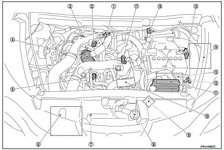
1. Boost control actuator
2. Turbocharger boost control solenoid
valve
3. A/F sensor 1
4. Recirculation valve
5. EVAP canister purge volume control
solenoid valve
6. Inter cooler
7. Refrigerant pressure sensor
Refer to HAC-12, "Component Parts
Location".
8. Cooling fan motor
9. Cooling fan control module
10. Electric throttle control actuator
(with built in throttle position sensor
and throttle control motor)
11. Relay box
• Cooling fan relay
• Fuel injector relay
• Fuel pump relay
12. Atmospheric pressure sensor
13. ECM
14. IPDM E/R
Refer to PCS-5, "Component Parts
Location".
15. Battery current sensor (with battery temperature sensor) 16. Mass air flow sensor (with intake air temperature sensor 1) 17. Turbocharger boost sensor (with intake air temperature sensor 2)
ENGINE COMPARTMENT
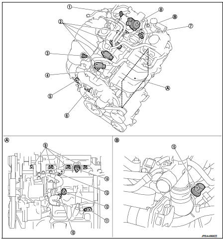
1. Exhaust valve timing control position
sensor
2. Ignition coil
(with power transistor)
3. A/F sensor 1
4. PCV valve
5. Exhaust valve timing control solenoid
valve
6. Intake valve timing control solenoid
valve
7. Camshaft position sensor (PHASE)
8. High pressure fuel pump
9. Fuel injector
10. Engine oil temperature sensor
11. Crankshaft position sensor (POS)
12. Engine oil pressure sensor
13. Knock sensor
14 Fuel rail pressure sensor
15. Engine coolant temperature sensor
A. Cylinder block left side B. Engine rear end
EXHAUST COMPARTMENT
2WD
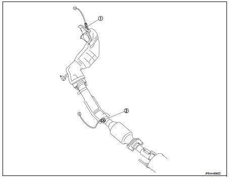
1. A/F sensor 1
2. Heated oxygen sensor 2
4WD
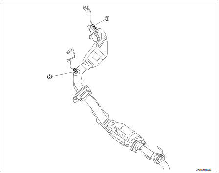
1. A/F sensor 1
2. Heated oxygen sensor 2
BODY COMPARTMENT
2WD
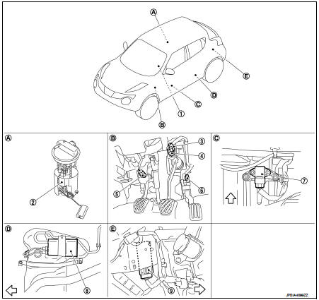
1. ASCD steering switch
2. Fuel level sensor unit, fuel filter and
fuel pump assembly
3. Brake pedal position switch
4. Stop lamp switch
5. Clutch pedal position switch
6. Accelerator pedal position sensor
7. G sensor
8. EVAP canister
9. Fuel pump control module (FPCM)
A. Under of right side second seat
B. Periphery of pedals
C. Under of driver's seat
D. Under of left side fuel tank
E. Behind the luggage side lower finisher
LH
 : Vehicle front
4WD
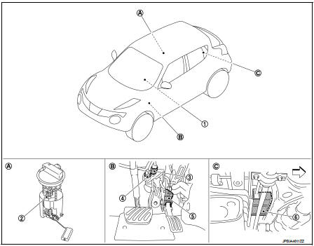
1. ASCD steering switch
2. Fuel level sensor unit, fuel filter and
fuel pump assembly
3. Stop lamp switch
4. Brake pedal position switch
5. Accelerator pedal position sensor
6. EVAP canister
A. Under of right side second seat
B. Periphery of pedals
C. Over the rear final drive assembly
: Vehicle front
Engine control system : Component Description
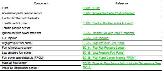
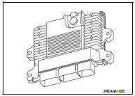
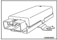
ECM
The ECM consists of a microcomputer and connectors for signal input and output and for power supply. The ECM controls the engine.
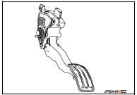
Accelerator Pedal Position Sensor
The accelerator pedal position sensor is installed on the upper end of the accelerator pedal assembly. The sensor detects the accelerator position and sends a signal to the ECM.
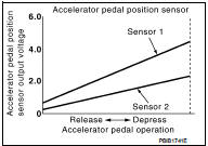
Accelerator pedal position sensor has two sensors. These sensors are a kind of potentiometers which transform the accelerator pedal position into output voltage, and emit the voltage signal to the ECM.
In addition, these sensors detect the opening and closing speed of the accelerator pedal and feed the voltage signals to the ECM. The ECM judges the current opening angle of the accelerator pedal from these signals and controls the throttle control motor based on these signals.
Idle position of the accelerator pedal is determined by the ECM receiving the signal from the accelerator pedal position sensor. The ECM uses this signal for the engine operation such as fuel cut.
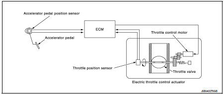
Electric Throttle Control Actuator
OUTLINE
Electric throttle control actuator consists of throttle body, throttle valve, throttle control motor and throttle position sensor
THROTTLE CONTROL MOTOR RELAY
Power supply for the throttle control motor is provided to the ECM via throttle control motor relay. The throttle control motor relay is ON/OFF controlled by the ECM. When the ignition switch is turned ON, the ECM sends an ON signal to throttle control motor relay and battery voltage is provided to the ECM. When the ignition switch is turned OFF, the ECM sends an OFF signal to throttle control motor relay and battery voltage is not provided to the ECM.
THROTTLE CONTROL MOTOR
The throttle control motor is operated by the ECM and it opens and closes the throttle valve.
The current opening angle of the throttle valve is detected by the throttle position sensor and it provides feedback to the ECM to control the throttle control motor to make the throttle valve opening angle properly in response to driving condition.
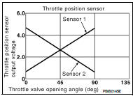
THROTTLE POSITION SENSOR
The throttle position sensor responds to the throttle valve movement.
The throttle position sensor has two sensors. These sensors are a kind of potentiometers which transform the throttle valve position into output voltage, and emit the voltage signal to the ECM. In addition, these sensors detect the opening and closing speed of the throttle valve and feed the voltage signals to the ECM. The ECM judges the current opening angle of the throttle valve from these signals and the ECM controls the throttle control motor to make the throttle valve opening angle properly in response to driving condition.
Ignition Coil With Power Transistor
The ignition signal from the ECM is sent to and amplified by the power transistor. The power transistor turns ON and OFF the ignition coil primary circuit. This ON/OFF operation induces the proper high voltage in the coil secondary circuit.
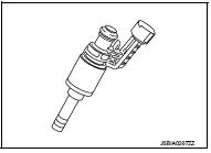
Fuel Injector
For the fuel injector, a high pressure fuel injector is used and this enables a high-pressure fuel injection at a high voltage within a short time. The ECM is equipped with an injector driver unit and actuates the fuel injector at a high voltage (approximately 65 V at the maximum).
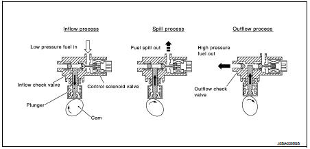
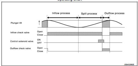
High Pressure Fuel Pump
The high pressure fuel pump is activated by the exhaust camshaft.
ECM controls the high pressure fuel pump control solenoid valve built into the high pressure fuel pump and adjusts the amount of discharge by changing the suction timing of the low pressure fuel.
Operating Description
Operating Chart
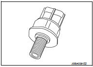
Fuel Rail Pressure Sensor
The fuel rail pressure (FRP) sensor is placed to the fuel rail and measures fuel pressure in the fuel rail. The sensor transmits voltage signal to the ECM. As the pressure increases, the voltage rises. The ECM controls the fuel pressure in the fuel rail by operating high pressure fuel pump. The ECM uses the signal from fuel rail pressure sensor as a feedback signal.
Low Pressure Fuel Pump
The low pressure fuel pump is integrated with a fuel pressure regulator and a fuel filter. This pump is build into the fuel tank.
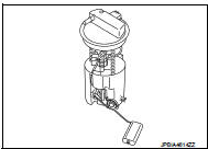
Fuel Pump Control Module (FPCM)
The fuel pump control module (FPCM) controls the discharging volume of the fuel pump by transmitting the FPCM control signals (Low/ Mid/High) depending on driving conditions.
Mass Air Flow Sensor (With Intake Air Temperature Sensor 1)
MASS AIR FLOW SENSOR
The mass air flow sensor (1) is placed in the stream of intake air. It measures the intake flow rate by measuring a part of the entire intake flow. The mass air flow sensor controls the temperature of the hot wire to a certain amount. The heat generated by the hot wire is reduced as the intake air flows around it. The more air, the greater the heat loss.
Therefore, the electric current supplied to hot wire is changed to maintain the temperature of the hot wire as air flow increases. The ECM detects the air flow by means of this current change.
INTAKE AIR TEMPERATURE SENSOR 1
The intake air temperature sensor 1 is built-into mass air flow sensor. The sensor detects intake air temperature and transmits a signal to the ECM.
The temperature sensing unit uses a thermistor which is sensitive to the change in temperature. Electrical resistance of the thermistor decreases in response to the temperature rise.
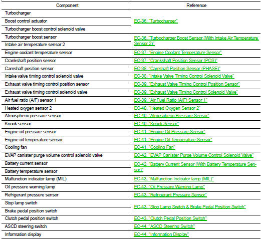
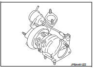
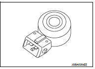
Turbocharger
Turbocharger boost is controlled by adjusting the pressure to the diaphragm of the boost control actuator.
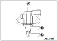
TURBOCHARGER BOOST CONTROL SOLENOID VALVE
Turbocharger boost control solenoid valve is ON/OFF duty controlled by ECM.
And it adjusts the pressure in the diaphragm of the boost control actuator. The longer the turbocharger boost control solenoid valve is ON, the higher the boost is increased.
A. From boost pipe
B. To boost control actuator
C. To Air cleaner
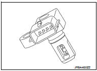
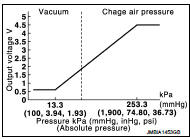
Turbocharger Boost Sensor (With Intake Air Temperature Sensor 2)
TURBOCHARGER BOOST SENSOR
The turbocharger boost sensor detects the pressure of the outlet side of the intercooler. When increasing the pressure, the output voltage of the sensor to the ECM increases.
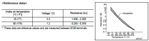
INTAKE AIR TEMPERATURE SENSOR 2
The intake air temperature sensor 2 is built-into turbocharger boost sensor. The sensor detects intake air temperature and transmits a signal to the ECM.
The temperature sensing unit uses a thermistor which is sensitive to the change in temperature. Electrical resistance of the thermistor decreases in response to the temperature rise.
Engine Coolant Temperature Sensor
The engine coolant temperature sensor is used to detect the engine coolant temperature. The sensor modifies a voltage signal from the ECM. The modified signal returns to the ECM as the engine coolant temperature input. The sensor uses a thermistor which is sensitive to the change in temperature. The electrical resistance of the thermistor decreases as temperature increases.
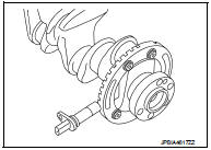
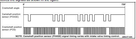
Crankshaft Position Sensor (POS)
The crankshaft position sensor (POS) is located on the oil pan facing the gear teeth (cogs) of the signal plate. It detects the fluctuation of the engine revolution.
The sensor consists of a permanent magnet and Hall IC.
When the engine is running, the high and low parts of the teeth cause the gap with the sensor to change.
The changing gap causes the magnetic field near the sensor to change.
Due to the changing magnetic field, the voltage from the sensor changes.
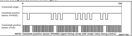
The ECM receives the voltage signal and detects the fluctuation of the engine revolution.
ECM receives the signals as shown in the figure.
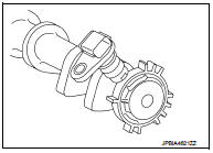
Camshaft Position Sensor (PHASE)
The camshaft position sensor (PHASE) senses the retraction of intake camshaft to identify a particular cylinder. The camshaft position sensor (PHASE) senses the piston position.
When the crankshaft position sensor (POS) system becomes inoperative, the camshaft position sensor (PHASE) provides various controls of engine parts instead, utilizing timing of cylinder identification signals.
The sensor consists of a permanent magnet and Hall IC.
When engine is running, the high and low parts of the teeth cause the gap with the sensor to change.
The changing gap causes the magnetic field near the sensor to change.
Due to the changing magnetic field, the voltage from the sensor changes.
ECM receives the signals as shown in the figure.
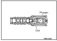
Intake Valve Timing Control Solenoid Valve
Intake valve timing control solenoid valve is activated by ON/OFF pulse duty (ratio) signals from the ECM.
The intake valve timing control solenoid valve changes the oil amount and direction of flow through intake valve timing control unit or stops oil flow.
The longer pulse width advances valve angle.
The shorter pulse width retards valve angle.
When ON and OFF pulse widths become equal, the solenoid valve stops oil pressure flow to fix the intake valve angle at the control position.
Exhaust Valve Timing Control Position Sensor
Exhaust valve timing control position sensor detects the protrusion of the signal plate installed to the exhaust camshaft front end.
This sensor signal is used for sensing a position of the exhaust camshaft.
This sensor uses a Hall IC.
Based on the position of the exhaust camshaft, ECM controls exhaust valve timing control solenoid valve to optimize the shut/open timing of exhaust valve for the driving condition.
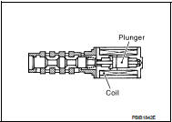
Exhaust Valve Timing Control Solenoid Valve
Exhaust valve timing control solenoid valve is activated by ON/OFF pulse duty (ratio) signals from the ECM.
The exhaust valve timing control solenoid valve changes the oil amount and direction of flow through exhaust valve timing control unit or stops oil flow.
The longer pulse width retards valve angle.
The shorter pulse width advances valve angle.
When ON and OFF pulse widths become equal, the solenoid valve stops oil pressure flow to fix the exhaust valve angle at the control position.
Air Fuel Ratio (A/F) Sensor 1
DESCRIPTION
The sensor element of the A/F sensor 1 is composed an electrode layer, which transports ions. It has a heater in the element.
The sensor is capable of precise measurement = 1, but also in the lean and rich range. Together with its control electronics, the sensor outputs a clear, continuous signal throughout a wide range.
The exhaust gas components diffuse through the diffusion layer at the sensor cell. An electrode layer is applied voltage, and this current relative oxygen density in lean. Also this current relative hydrocarbon density in rich.
Therefore, the A/F sensor 1 is able to indicate air fuel ratio by this electrode layer of current. In addition, a heater is integrated in the sensor to ensure the required operating temperature of approximately 760°C (1,400°F).
A/F SENSOR 1 HEATER
A/F sensor 1 heater is integrated in the sensor.
The ECM performs ON/OFF duty control of the A/F sensor 1 heater corresponding to the engine operating condition to keep the temperature of A/F sensor 1 element within the specified range.
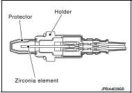
Heated Oxygen Sensor 2
DESCRIPTION
The heated oxygen sensor 2, after three way catalyst (manifold), monitors the oxygen level in the exhaust gas on each bank.
Even if switching characteristics of the air fuel ratio (A/F) sensor 1 are shifted, the air fuel ratio is controlled to stoichiometric, by the signal from the heated oxygen sensor 2.
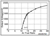
This sensor is made of ceramic zirconia. The zirconia generates voltage from approximately 1 V in richer conditions to 0 V in leaner conditions.
Under normal conditions the heated oxygen sensor 2 is not used for engine control operation.
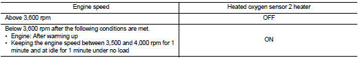
HEATED OXYGEN SENSOR 2 HEATER
Heated oxygen sensor 2 heater is integrated in the sensor.
The ECM performs ON/OFF control of the heated oxygen sensor 2 heater corresponding to the engine speed, amount of intake air and engine coolant temperature.
Atmospheric Pressure Sensor
The atmospheric pressure sensor is placed at ECM bracket. It detects atmospheric pressure and sends the voltage signal to the ECM.
The sensor uses a silicon diaphragm which is sensitive to the change in pressure. As the pressure increases, the voltage rises.
Knock Sensor
The knock sensor is attached to the cylinder block. It senses engine knocking using a piezoelectric element. A knocking vibration from the cylinder block is sensed as vibrational pressure. This pressure is converted into a voltage signal and sent to the ECM.
Engine Oil Pressure Sensor
The engine oil pressure (EOP) sensor is detects engine oil pressure and transmits a voltage signal to the ECM.
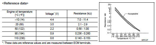
Engine Oil Temperature Sensor
The engine oil temperature sensor is used to detect the engine oil temperature. The sensor modifies a voltage signal from the ECM.
The modified signal returns to the ECM as the engine oil temperature input. The sensor uses a thermistor which is sensitive to the change in temperature. The electrical resistance of the thermistor decreases as temperature increases.
Cooling Fan
COOLING FAN CONTROL MODULE
Cooling fan control module receives ON/OFF pulse duty signal from IPDM E/R. Corresponding to this ON/OFF pulse duty signal, cooling fan control module sends cooling fan motor operating voltage to cooling fan motor.
The revolution speed of cooling fan motor is controlled by duty cycle of the voltage.
COOLING FAN MOTOR
Cooling fan motor receives cooling fan motor operating voltage from cooling fan control module. The revolution speed of cooling fan motor is controlled by duty cycle of the voltage.
EVAP Canister Purge Volume Control Solenoid Valve
The EVAP canister purge volume control solenoid valve uses a ON/ OFF duty to control the flow rate of fuel vapor from the EVAP canister.
The EVAP canister purge volume control solenoid valve is moved by ON/OFF pulses from the ECM. The longer the ON pulse, the greater the amount of fuel vapor that will flow through the valve.
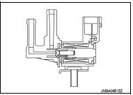
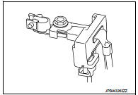
Battery Current Sensor (With Battery Temperature Sensor)
OUTLINE
The power generation voltage variable control enables fuel consumption to be decreased by reducing the engine load which is caused by the power generation of the generator.
Based on sensor signals, ECM judges whether or not the power generation voltage variable control is performed. When performing the power generation voltage variable control, ECM calculates the target power generation voltage based on the sensor signal. And ECM sends the calculated value as the power generation command value to IPDM E/R. For the details of the power generation voltage variable control, refer toCHG-9, "POWER GENERATION VOLTAGE VARIABLE CONTROL SYSTEM : System Description (Gasoline Engine Models)".
CAUTION:
Never connect the electrical component or the ground wire directly to the
battery terminal. The connection
causes the malfunction of the power generation voltage variable control, and
then the battery
discharge may occur.
BATTERY CURRENT SENSOR
The battery current sensor is installed to the battery negative cable. The sensor measures the charging/discharging current of the battery.
BATTERY TEMPERATURE SENSOR
Battery temperature sensor is integrated in battery current sensor.
The sensor measures temperature around the battery.
The electrical resistance of the thermistor decreases as temperature increases.
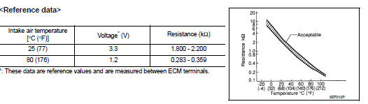
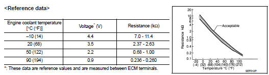
<Reference data>
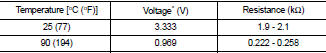
*: These data are reference values and are measured between battery temperature sensor signal terminal and sensor ground.
Malfunction Indicator lamp (MIL)
Malfunction Indicator lamp (MIL) is located on the combination meter.
MIL will illuminate when the ignition switch is turned ON without the engine running. This is a bulb check.
When the engine is started, MIL should turn OFF. If the MIL remains illuminated, the on board diagnostic system has detected an engine system malfunction.
For details, refer to EC-79, "DIAGNOSIS DESCRIPTION : Malfunction Indicator Lamp (MIL)".
Oil Pressure Warning Lamp
Oil pressure warning lamp is located on the combination meter.
It indicates the low pressure of the engine oil and the malfunction of the engine oil pressure system.
Combination meter turns the oil pressure warning lamp ON/OFF according to the oil pressure warning lamp signal received from ECM via CAN communication.
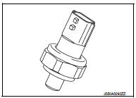
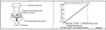
Refrigerant Pressure Sensor
The refrigerant pressure sensor is installed at the condenser of the air conditioner system. The sensor uses an electrostatic volume pressure transducer to convert refrigerant pressure to voltage. The voltage signal is sent to ECM, and ECM controls cooling fan system.
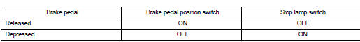
Stop Lamp Switch & Brake Pedal Position Switch
Stop lamp switch and brake pedal position switch are installed to brake pedal bracket.
ECM detects the state of the brake pedal by those two types of input (ON/OFF signal).
Clutch Pedal Position Switch
When the clutch pedal is depressed, the clutch pedal position switch turns OFF and the clutch pedal position switch signal is sent to the ECM. The ECM judges the clutch pedal conditions via the signal (ON or OFF).
ASCD Steering Switch
ASCD steering switch has variant values of electrical resistance for each button. ECM reads voltage variation of switch, and determines which button is operated.
Information Display
The operation mode of the ASCD and speed limiter are indicated on the information display in the combination meter.
ECM transmits the status signal to the combination meter via CAN communication according to ASCD and speed limiter operation.

 Structure and operation
Positive Crankcase Ventilation
This system returns blow-by gas to the intake manifold.
The positive crankcase ventilation (PCV) valve is provided to conduct crankcase
blow-by gas to the intake ...
Other materials:
Positive crankcase ventilation
Inspection
1.CHECK PCV VALVE
With engine running at idle, remove PCV valve from rocker cover. A
properly working valve makes a hissing noise as air passes through
it. A strong vacuum should be felt immediately when a finger is
placed over valve inlet.
Is the inspection result normal?
YES &g ...
Steering wheel
Exploded View
1. Steering wheel
: Always replace after every
disassembly.
: N·m (kg-m, ft-lb)
Removal and Installation
REMOVAL
NOTE:
When reconnecting spiral cable, fix cable with a tape so that fixing case and
rotating part keep aligned. This
will omit neutral position alignment proce ...
P0848 transmission fluid pressure SEN/SW B
DTC Logic
DTC DETECTION LOGIC
DTC CONFIRMATION PROCEDURE
1.PREPARATION BEFORE WORK
If another "DTC CONFIRMATION PROCEDURE" occurs just before, the ignition
switch OFF and wait for at
least 10 seconds, then perform the next test.
>> GO TO 2.
2.CHECK DTC DETECTION
With ...
