Nissan Juke Service and Repair Manual : Electric ignition system
Electric ignition system : System Diagram
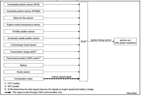
Electric ignition system : System Description
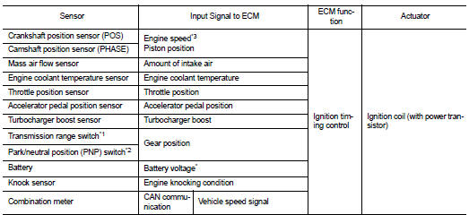
INPUT/OUTPUT SIGNAL CHART
*1: CVT models
*2: M/T models
*3: ECM determines the start signal status by the signals of engine speed and
battery voltage.
SYSTEM DESCRIPTION
Firing order: 1 - 3 - 4 - 2 The ignition timing is controlled by the ECM to maintain the best air-fuel ratio for every running condition of the engine. The ignition timing data is stored in the ECM.
The ECM receives information such as the injection pulse width and camshaft position sensor (PHASE) signal.
Computing this information, ignition signals are transmitted to the power transistor.
During the following conditions, the ignition timing is revised by the ECM according to the other data stored in the ECM.
• At starting
• During warm-up
• At idle
• At low battery voltage
• During acceleration
The knock sensor retard system is designed only for emergencies. The basic ignition timing is programmed within the anti-knocking zone, if recommended fuel is used under dry conditions. The retard system does not operate under normal driving conditions. If engine knocking occurs, the knock sensor monitors the condition.
The signal is transmitted to the ECM. The ECM retards the ignition timing to eliminate the knocking condition.
 Fuel pressure control
Fuel pressure control : System Diagram
Fuel pressure controlL : System Description
INPUT/OUTPUT SIGNAL CHART
*: ECM determines the start signal status by the engine speed signal and
battery v ...
 Intake valve timing control
Intake valve timing control : System Diagram
Intake valve timing control : System Description
INPUT/OUTPUT SIGNAL CHART
SYSTEM DESCRIPTION
This mechanism hydraulically controls cam phases co ...
Other materials:
P1550 battery current sensor
DTC Logic
DTC DETECTION LOGIC
DTC CONFIRMATION PROCEDURE
1.PRECONDITIONING
If DTC Confirmation Procedure has been previously conducted, always perform
the following before conducting
the next test.
1. Turn ignition switch OFF and wait at least 10 seconds.
2. Turn ignition switch ON.
3. ...
Excessive consumption
Description
CHART 15:EXCESSIVE CONSUMPTION
Diagnosis Procedure
1.CHECK ECM POWER SUPPLY AND GROUND CIRCUIT
Check ECM power supply and ground circuit. Refer to EC-885, "Diagnosis
Procedure".
Is the inspection result normal?
YES >> GO TO 2.
NO >> Repair or replace ha ...
Engine idle speed too high
Description
CHART 5: ENGINE IDLE SPEED TOO HIGH
Diagnosis Procedure
1.CHECK ECM POWER SUPPLY AND GROUND CIRCUIT
Check ECM power supply and ground circuit. Refer to EC-885, "Diagnosis
Procedure".
Is the inspection result normal?
YES >> GO TO 2.
NO >> Repair or repla ...
