Nissan Juke Service and Repair Manual : Electric controlled coupling
Exploded View
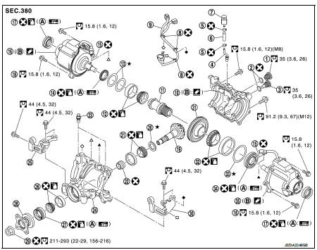
1. Filler plug
2. Gasket
3. Drain plug
4. Breather tube
5. Clip
6. Breather hose
7. Breather
8. sub-harness clip
9. sub-harness
10. Rear cover
11. Center stem
12. Side bearing (right)
13. Side bearing adjusting shim (right)
14. Side oil seal (right)
15. Connector clip
16. Electric controlled coupling (right)
17. Electric controlled coupling oil seal
18. Reamer bolt
19. Drive pinion
20. Drive pinion adjusting shim
21. Pinion rear bearing
22. Collapsible spacer
23. Breather
24. Gear carrier
25. Carrier bracket (right)
26. Pinion front bearing
27. Front oil seal
28. Companion flange
29. Drive pinion lock nut
30. Carrier bracket (left)
31. Drive gear
32. Side bearing (left)
33. Side bearing adjusting shim (left)
34. Electric controlled coupling (left)
35. Side oil seal (left)
A. Oil seal lip B. Gear carrier mounting face
 : N·m (kg-m, ft-lb)
 : Always replace after every
disassembly.
 : Apply gear oil.
 : Apply anti-corrosive oil.
 : Apply multi purpose grease
 : Apply Genuine Liquid Gasket 1217
or equivalent.
 : Select with proper thickness.
Disassembly
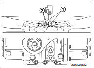
1. Disconnect electric controlled coupling connector (1) from subharness (2).
2. Remove connector clip (  )
)
from final drive assembly.
3. Remove electric controlled coupling from final drive assembly.
4. Remove sub-harness from final drive assembly.
CAUTION:
Remove sub-harness only when necessary.
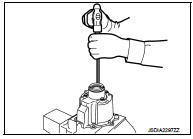
5. Remove electric controlled coupling oil seals from electric controlled coupling, using a suitable tool.
CAUTION:
Never damage electric controlled coupling.
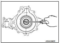
6. Remove side oil seals with a suitable tool.
CAUTION:
Never damage gear carrier and rear cover.
7. Perform inspection after disassembly. Refer to DLN-150, "Inspection".
Assembly
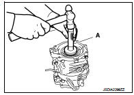
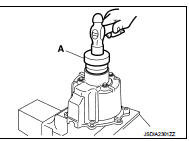
1. Install side oil seal (right side) until it becomes flush with the carrier end, using the drift (A) (SST: KV38100200).
CAUTION:
• Never reuse oil seals.
• When installing, never incline oil seals.
• Apply multi-purpose grease onto oil seal lips, and gear oil onto the circumference of oil seal.
2. Install side oil seal (left side) until it becomes flush with the carrier end, using the drift (A) (SST: KV38100500).
CAUTION:
• Never reuse oil seals.
• When installing, never incline oil seals.
• Apply multi-purpose grease onto oil seal lips, and gear oil onto the circumference of oil seal.
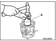
3. Install electric controlled coupling oil seals to electric controlled coupling, using the drift (A) (SST: KV38109700).
NOTE
:
The use of the special service tool satisfies the mounting dimensions.
CAUTION:
• Never reuse oil seals.
• When installing, never incline oil seals.
• Apply multi-purpose grease onto oil seal lips, and gear oil onto the circumference of oil seal.
4. Install new sub-harness clip to sub-harness.
CAUTION:
• Check original mounting dimensions to install clip to the original position.
• Baffle pin must be functioning normally.
5. Install sub-harness to final drive assembly.
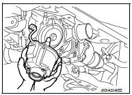
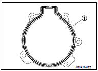
6. Apply liquid gasket (1) to mating surface of coupling cover.
CAUTION:
• Remove old gasket adhering to the mounting surfaces.
Also remove any moisture, oil, or foreign material adhering to the mounting surfaces.
• Overlap both ends of the bead for at least 3 mm (0.12 in).
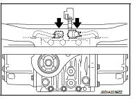
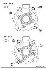
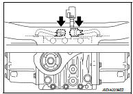
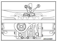
7. Install electric controlled coupling (1) to spline of stem center with grommet of harness facing upward, temporarily tighten reamer bolts (2) to the positions shown in the figure.
8. Tighten reamer bolts and coupling cover mounting bolts to the specified torque.
 : Vehicle front
CAUTION:
Never allow harness to get caught in the bolt.
9. Install the new connector clip (
) to final drive assembly.
CAUTION:
Never reuse connector clip.
10. Connect electric controlled coupling connector (1) to sub-harness (2).
11. When oil leaks while removing, check oil level after the installation.
Refer to DLN-132, "Inspection".
Inspection
INSPECTION AFTER DISASSEMBLY
Oil Seal
• Whenever disassembled, replace.
• If wear, deterioration of adherence (sealing force lips), or damage is detected on the lips, replace them.

 Center stem assembly
Exploded View
1. Filler plug
2. Gasket
3. Drain plug
4. Breather tube
5. Clip
6. Breather hose
7. Breather
8. sub-harness clip
9. sub-harness
10. Rear cover
11. Center stem
12. Si ...
Other materials:
Symptom diagnosis
COMBINATION SWITCH SYSTEM SYMPTOMS
Symptom Table
1. Perform “Data Monitor” of CONSULT-III to check for any malfunctioning
item.
2. Check the malfunction combinations.
3. Identify the malfunctioning part from the agreed combination and repair or
replace the part.
...
MDU branch line circuit
Diagnosis Procedure
1.CHECK CONNECTOR
1. Turn the ignition switch OFF.
2. Disconnect the battery cable from the negative terminal.
3. Check the terminals and connectors of the multi display unit for damage, bend
and loose connection (unit
side and connector side).
Is the inspection result ...
P1572 ASCD brake switch
DTC Logic
DTC DETECTION LOGIC
NOTE:
• If DTC P1572 is displayed with DTC P0605, first perform the trouble diagnosis
for DTC P0605. Refer
to EC-683, "DTC Logic".
• This self-diagnosis has the one trip detection logic. When malfunction A is
detected, DTC is not
stored in ECM memory ...
