Nissan Juke Service and Repair Manual : Ecu diagnosis information
TCM
Reference Value
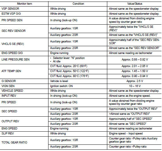
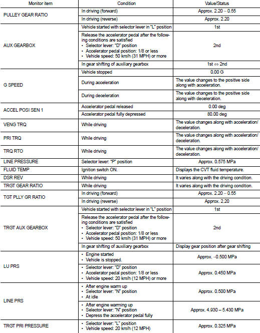
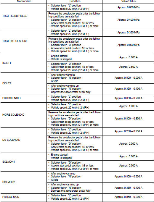
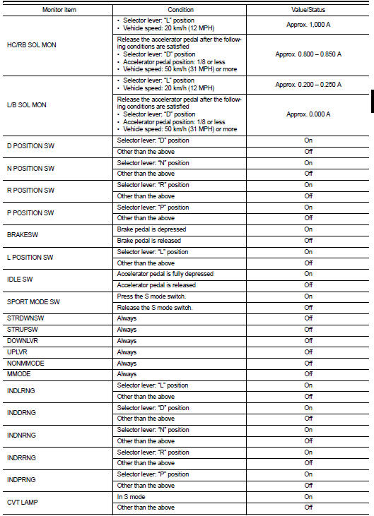
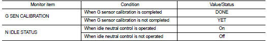
CONSULT-III DATA MONITOR STANDARD VALUE
• In CONSULT-III, electric shift timing or lock-up timing, i.e. operation timing of each solenoid valve, is displayed.
Therefore, if there is an obvious difference between the shift timing estimated from a shift shock (or engine speed variations) and that shown on the CONSULT-III, the mechanism parts (including the hydraulic circuit) excluding the solenoids and sensors may be malfunctioning. In this case, check the mechanical parts following the appropriate diagnosis procedure.
• Shift point (gear position) displayed on CONSULT-III slightly differs from shift pattern described in Service Manual. This is due to the following reasons.
- Actual shift pattern may vary slightly within specified tolerances.
- While shift pattern described in Service Manual indicates start of each shift, CONSULT-III shows gear position at end of shift.
- The solenoid display (ON/OFF) on CONSULT-III is changed at the start of gear shifting. In contrast, the gear position display is changed at the time when gear shifting calculated in the control unit is completed.
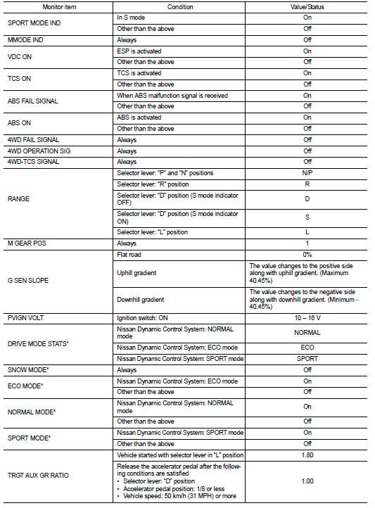
*: With Nissan Dynamic Control System
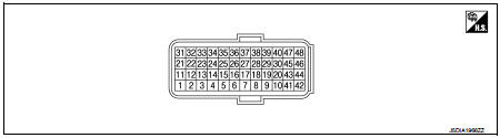
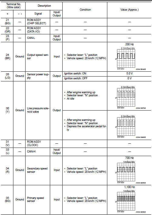
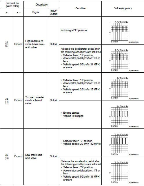
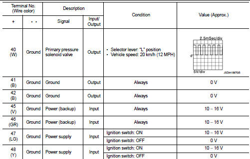
TERMINAL LAYOUT
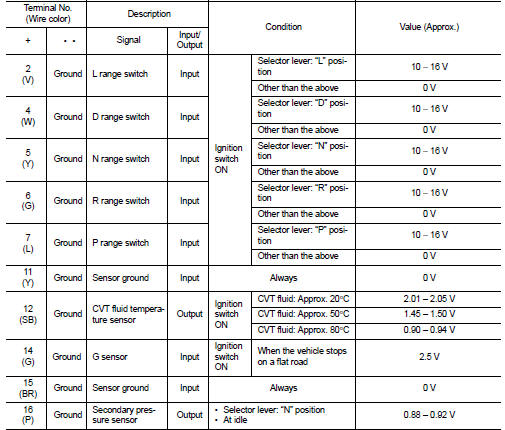
INPUT/OUTPUT SIGNAL STANDARD
Fail-Safe
TCM has a fail-safe mode. The mode functions so that operation can be continued even if the signal circuit of the main electronically controlled input/output parts is damaged.
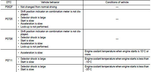
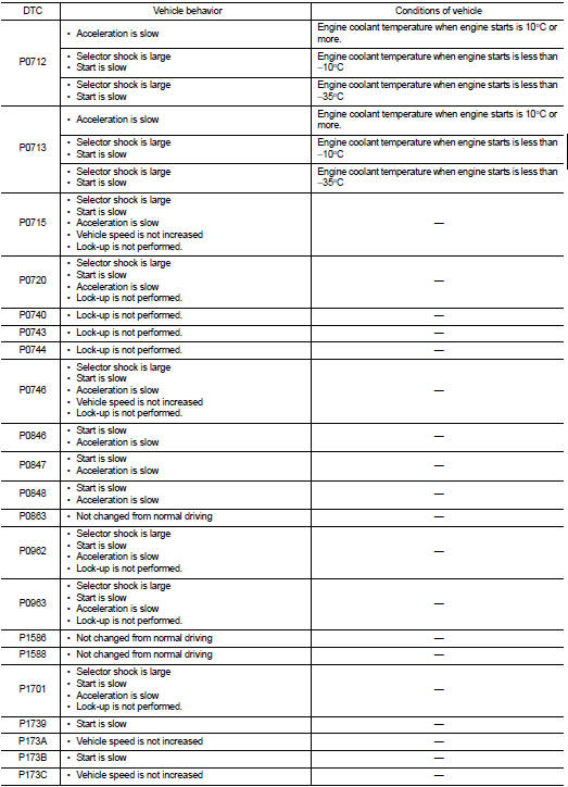
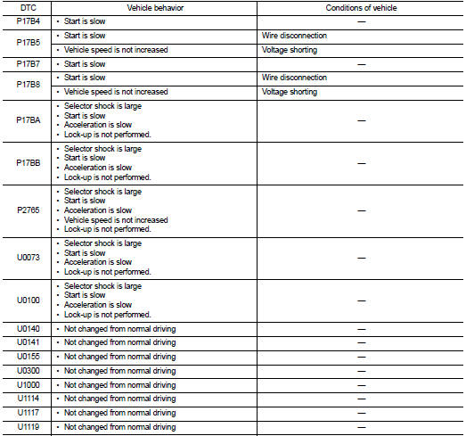
If the vehicle shows following behaviors including "poor acceleration", a malfunction of the applicable system is detected by TCM and the vehicle may be in a fail-safe mode. At this time, check the DTC code and perform inspection and repair according to the malfunction diagnosis procedures.
Fail-safe function
Protection control
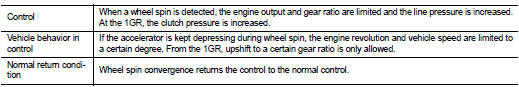
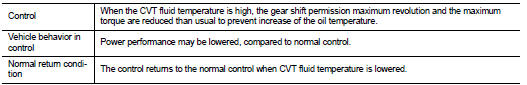
The TCM becomes the protection control status temporarily to protect the safety when the safety of TCM and transmission is lost. It automatically returns to the normal status if the safety is secured.
The TCM has the following protection control.
CONTROL FOR WHEEL SPIN
CONTROL WHEN FLUID TEMPERATURE IS HIG
TORQUE IS REDUCED WHEN DRIVING WITH THE REVERSE GEAR
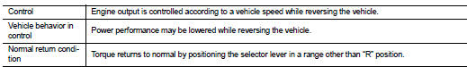
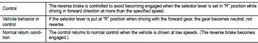
REVERSE PROHIBIT CONTRO
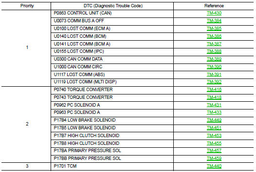
DTC Inspection Priority Chart
If multiple malfunction codes are detected at the same time, check each code according to the DTC check priority list below.
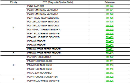
DTC Index
NOTE
:
• If multiple malfunction codes are detected at the same time, check each code
according to the "DTC check
priority list". TM-365, "DTC Inspection Priority Chart".
• The ignition counter is displayed in “FFD”. Refer to TM-347, "CONSULT-III Function (TRANSMISSION)".
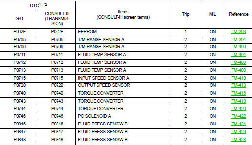
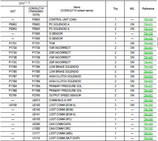
*1: These numbers are specified by SAE J2012/ISO 15031-6.
*2: The DTC number of the 1st trip is the same as the DTC number.
 Diagnosis system (TCM)
Diagnosis description : 1 Trip Detection Diagnosis and 2 Trip Detection
Diagnosis
NOTE:
“Start the engine and turn OFF the ignition switch after warm-up.” This is
defined as 1 trip.
1 TRIP DE ...
 Wiring diagram
...
Other materials:
Air cleaner filter
Removal and Installation
REMOVAL
1. Remove air duct assembly (duct side) (1).
2. Unhook the tabs (A) of both ends of the air cleaner cover.
3. Remove the air cleaner filter (1) and air cleaner body (2) from
the air cleaner case.
4. Remove the air cleaner filter from the air cleaner body.
...
Front drive shaft
Exploded View
LEFT SIDE
1. Circular clip
2. Dust shield
3. Housing assembly
4. Boot band
5. Boot
6. Damper band
7. Dynamic damper
8. Circular clip
9. Joint sub-assembly
: Wheel side
: Fill NISSAN Genuine grease or
equivalent.
: Always replace after every
disassembly.
RIGHT ...
Door lock actuator
Driver side
DRIVER SIDE : Component Function Check
1.CHECK FUNCTION
1. Select “DOOR LOCK” of “BCM” using CONSULT-III.
2. Select “DOOR LOCK” in “ACTIVE TEST” mode.
3. Check that the function operates normally according to the following
conditions.
Is the inspection result normal?
YES >& ...
