Nissan Juke Service and Repair Manual : ECU diagnosis information
4WD control module
Reference Value
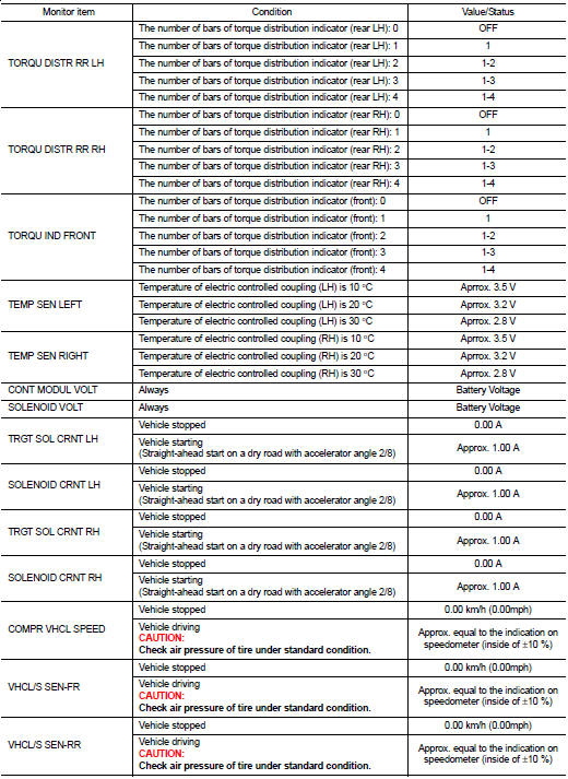
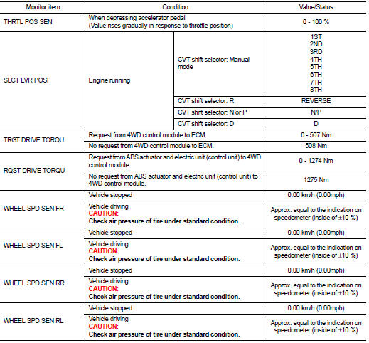
VALUES ON THE DIAGNOSIS TOOL
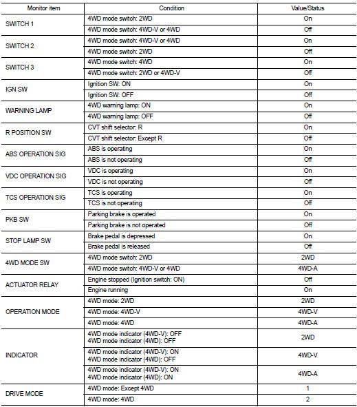
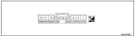
TERMINAL LAYOUT
PHYSICAL VALUES
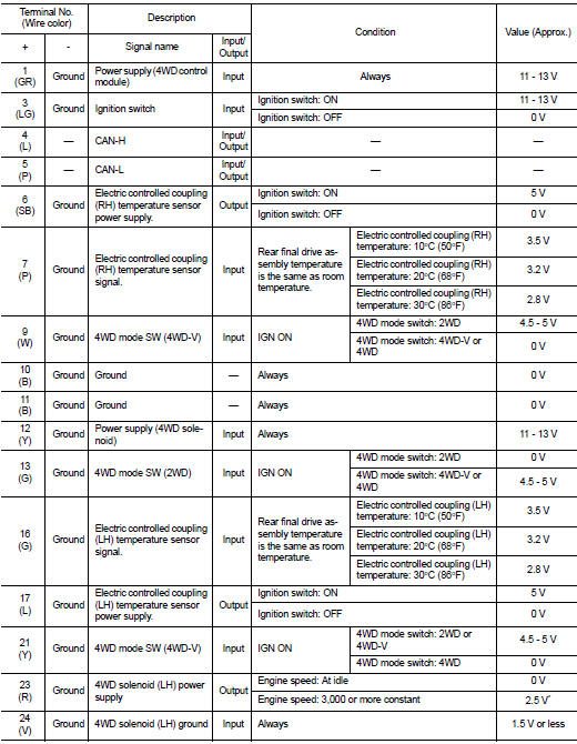
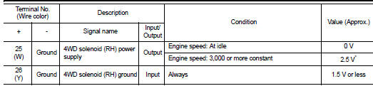
*: The values are changed by throttle opening and engine speed.
CAUTION:
When using circuit tester to measure voltage for inspection, be sure not to
extend forcibly any connector
terminals.
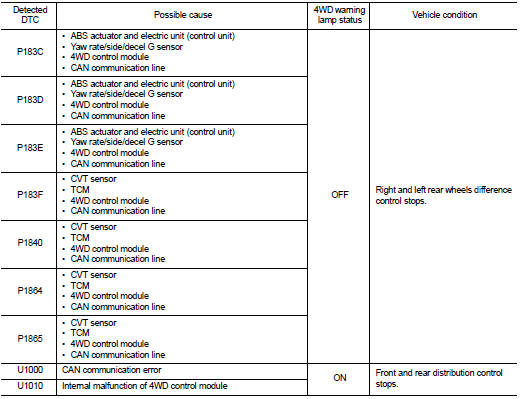
Fail-safe
When a system malfunction occurs, the 4WD warning lamp turns ON and the 4WD control becomes 2WD state.
Protection Function
4WD system activates its protection function (shuts down 4WD system temporarily) if 4WD system detects high load continuously, the front wheel tire size differs from the rear tire size or the rear RH wheel tire size differs from the rear LH tire size. (4WD system is automatically restored if 4WD system no longer detects any overload or the tire size difference is eliminated.)
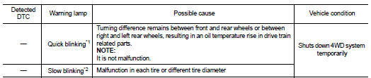
*1: 2 times/second (blinking for approximately 1 minute and then turned
OFF)
*2: 1 time/2 seconds (continuing to blink until ignition switch is turned OFF)
NOTE
:
• If the warning lamp blinks slowly during driving but remains OFF after the
engine is restarted, the system is
normal. If it again blinks slowly after driving for some time, vehicle must be
inspected.
• When there is a difference of revolution speed between the front and rear wheel the shift occasionally changes to direct 4-wheel driving conditions automatically. This is not a malfunction.
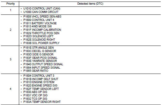
DTC Inspection Priority Chart
If some DTCs are displayed at the same time, perform inspections one by one based on the following priority chart.
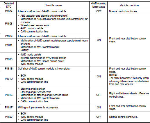
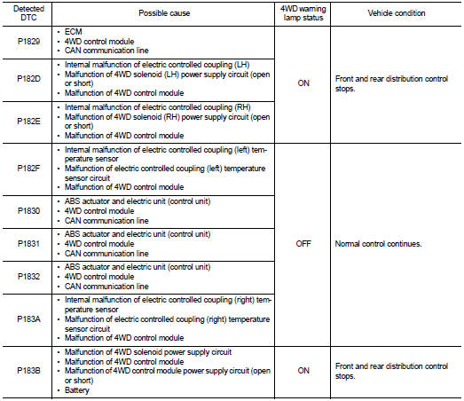
DTC Index
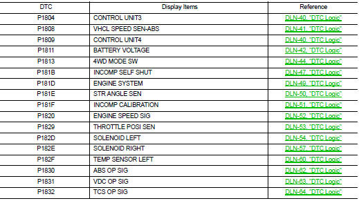
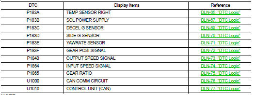
NOTE
:
If some DTCs are displayed at the same time, refer to DLN-33, "DTC Inspection
Priority Chart".
 Diagnosis system (4WD control module)
CONSULT-III Function
APPLICATION ITEMS
CONSULT-III can display each diagnostic item using the diagnostic test modes
as follows.
*: The following diagnosis information is erased by erasing.
• ...
 Wiring diagram
4WD SYSTEM
Wiring Diagram
For connector terminal arrangements, harness layouts, and alphabets in a
(option abbreviation; if not
described in wiring diagram), refer to GI-12, "Connector Inform ...
Other materials:
Removal and Installation
REMOVAL
1. Separate the rear propeller shaft. Refer to DLN-121, "Removal and
Installation".
2. Remove right side drive shaft. Refer to FAX-24, "RIGHT SIDE : Removal and
Installation".
3. Remove catalyst convertor support bracket (RH). EM-35, "4WD : Removal and
Insta ...
Turbocharger
Exploded View
1. Heat insulator
2. Actuator hose
3. Clamp
4. Turbocharger inlet tube
5. Gasket
6. Gasket
7. Clamp
8. Oil outlet hose
9. Oil return pipe
10. Oil supply tube
11. O-ring
12. O-ring
13. Turbocharger
14. Eye bolt
15. Gasket
16. Oil supply tube
A. To EVAP canis ...
Magnet clutch
Component Function Check
1.CHECK MAGNET CLUTCH OPERATION
Perform auto active test of IPDM E/R. Refer to PCS-12, "Diagnosis
Description" (with Intelligent Key) or PCS-
43, "Diagnosis Description" (without Intelligent Key).
Does it operate normally?
YES >> INSPECTION ...
