Nissan Juke Service and Repair Manual : Duct and grille
Exploded View
FRONT
LHD models
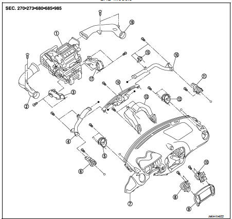
1. A/C unit assembly
2. Side ventilator duct LH
3. Foot duct LH
4. Side defroster nozzle LH
5. Side ventilator grille LH
6. Side defroster grille LH
7. Instrument panel assembly
8. Center ventilator grille LH
9. Cluster lid C
10. Center ventilator grille RH
11. Side defroster grille RH
12. Side ventilator grille RH
13. Center ventilator duct
14. Front defroster nozzle
15. Instrument panel bracket
16. Side defroster nozzle RH
17. Foot duct RH
18. Side ventilator duct RH
 : Pawl
REAR
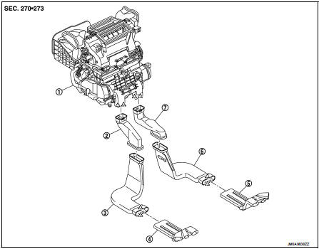
1. A/C unit assembly 2. Rear heater duct 1 LH* 3. Rear heater duct 2 LH* 4. Rear heater duct 3 LH* 5. Rear heater duct 1 RH* 6. Rear heater duct 2 RH* 7. Rear heater duct 3 RH*
: Pawl
*: Only LHD models for cold areas.
FRONT
RHD models
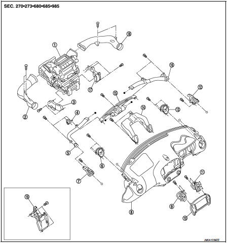
1. A/C unit assembly
2. Side ventilator duct LH
3. Foot duct LH
4. Instrument panel bracket
5. Side defroster nozzle LH
6. Side ventilator grille LH
7. Side defroster grille LH
8. Instrument panel assembly
9. Center ventilator grille LH
10. Cluster lid C
11. Center ventilator grille RH
12. Side defroster grille RH
13. Side ventilator grille RH
14. Center ventilator duct
15. Front defroster nozzle
16. Side defroster nozzle RH
17. Foot duct RH
18. Side ventilator duct RH
19. Foot duct RH (2WD models)
: Pawl
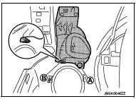
Center ventilator grille
CENTER VENTILATOR GRILLE : Removal and Installation
REMOVAL
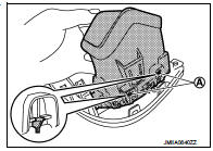
1. Remove cluster lid C. Refer to IP-13, "Removal and Installation".
2. Remove fixing screws (A).
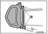
3. Disengage fixing pawls (A), and then remove center ventilator grille from cluster lid C.
INSTALLATION Install in the reverse order of removal.
SIDE DEFROSTER NOZZLE : Removal and Installation
REMOVAL
Driver side
1. Remove instrument panel assembly. Refer to IP-13, "Removal and
Installation".
2. Remove fixing screws (A), and then remove side defroster nozzle from instrument panel assembly.
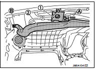
Passenger side
1. Remove instrument panel assembly. Refer to IP-13, "Removal and
Installation".
2. Remove fixing screws (A), and then remove instrument panel bracket (1).
3. Remove fixing screw (B), and then remove side defroster nozzle (2) from instrument panel assembly.
INSTALLATION
Install in the reverse order of removal.
SIDE VENTILATOR GRILLE : Removal and Installation
REMOVAL
1. Remove instrument panel assembly. Refer to IP-13, "Removal and Installation".
2. Remove fixing screws (A), and then remove side ventilator grille from instrument panel assembly.
INSTALLATION
Install in the reverse order of removal.
SIDE DEFROSTER GRILLE : Removal and Installation
REMOVAL
1. Remove instrument panel assembly. Refer to IP-13, "Removal and Installation".
2. Remove side defroster nozzle. Refer to VTL-10, "SIDE DEFROSTER NOZZLE : Removal and Installation".
3. Remove fixing screw (A) and disengage fixing pawl (B), and then remove side defroster grille from instrument panel assembly.
INSTALLATION
Install in the reverse order of removal
Front defroster nozzle
FRONT DEFROSTER NOZZLE : Removal and Installation
REMOVAL
1. Remove instrument panel assembly. Refer to IP-13, "Removal and Installation".
2. Remove side defroster nozzle. Refer to VTL-10, "SIDE DEFROSTER NOZZLE : Removal and Installation".
3. Remove fixing screw (A), and then remove front defroster nozzle from instrument panel assembly.
INSTALLATION
Install in the reverse order of removal.
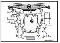
Center ventilator duct
CENTER VENTILATOR DUCT : Removal and Installation
REMOVAL
1. Remove instrument panel assembly. Refer to IP-13, "Removal and Installation".
2. Remove side defroster nozzle (LH and RH). Refer to VTL-10, "SIDE DEFROSTER NOZZLE : Removal and Installation".
3. Remove front defroster nozzle. Refer to VTL-11, "FRONT DEFROSTER NOZZLE : Removal and Installation".
4. Remove fixing screws (A), and then remove center ventilator duct from instrument panel assembly.
INSTALLATION
Install in the reverse order of removal.
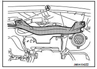
Side ventilator duct : Removal and Installation
REMOVAL
1. Remove instrument panel assembly. Refer to IP-13, "Removal and Installation".
2. Remove fixing screws (A), and then remove side ventilator duct (LH and RH) from the vehicle.
INSTALLATION
Install in the reverse order of removal.
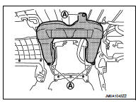
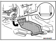
Rear heater duct 1 : Removal and Installation
REMOVAL
1. Remove center console assembly. Refer to IP-23, "Removal and Installation".
2. Disengage fixing pawls, and then remove rear heater duct 1 (LH and RH) from A/C unit assembly.
 : Pawl
INSTALLATION
Install in the reverse order of removal.
Rear heater duct 2 : Removal and Installation
REMOVAL
1. Remove center console assembly. Refer to IP-23, "Removal and Installation".
2. Remove front seat assmbly. Refer to SE-19, "Removal and Installation".
3. Remove front kicking plate inner and rear kicking plate inner. Refer to INT-19, "KICKING PLATE INNER : Removal and Installation".
4. Remove center pillar lower garnish. Refer to INT-20, "CENTER PILLAR LOWER GARNISH : Removal and Installation".
5. Remove dash side finisher. Refer to INT-20, "DASH SIDE FINISHER : Removal and Installation".
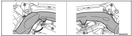
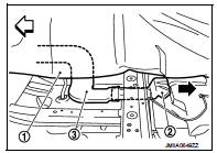
6. Remove rear heater duct 2.
• Peel off floor carpet (1).
• Remove rear heater duct 3 (2) from rear heater duct 2 (3).
 : Vehicle front
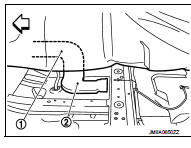
• Remove front floor spacer, and then remove rear heater duct 2 (2) from rear heater duct 1 (1).
 : Vehicle front
INSTALLATION
Install in the reverse order of removal.
Foot duct : Removal and Installation
REMOVAL
Driver side
1. Remove instrument lower panel. Refer to IP-13, "Removal and Installation".
2. Remove foot duct (LH/RH).
• Disconnect harness connector.
• Remove harness connector mounting clamp.
• Remove fixing screws, and then remove foot duct (LH/RH).
Passenger side
1. Remove glove box assembly. Refer to IP-13, "Removal and Installation".
2. Remove fixing screws, and then remove foot duct (LH/RH).
INSTALLATION
Install in the reverse order of removal.

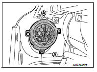
 Blower motor
Exploded View
2WD models
1. A/C unit assembly
2. Fan control amp.*1
3. Blower fan resistor*2
4. Blower motor
5. Blower motor cover
• *1: Automatic air conditioner
• *2: Manual air conditi ...
Other materials:
P0963 pressure control solenoid A
DTC Logic
DTC DETECTION LOGIC
DTC CONFIRMATION PROCEDURE
1.PREPARATION BEFORE WORK
If another "DTC CONFIRMATION PROCEDURE" occurs just before, turn ignition
switch OFF and wait for at
least 10 seconds, then perform the next test.
>> GO TO 2.
2.CHECK DTC DETECTION
1. S ...
On board diagnostic (OBD) system
Diagnosis Description
This system is an on board diagnostic system that records exhaust
emission-related diagnostic information
and detects a sensors/actuator-related malfunction. A malfunction is indicated
by the malfunction indicator
lamp (MIL) and stored in ECU memory as a DTC. The diagnos ...
Remote keyless entry system
Remote keyless entry function
REMOTE KEYLESS ENTRY FUNCTION : System Diagram
REMOTE KEYLESS ENTRY FUNCTION : System Description
DOOR LOCK AND UNLOCK OPERATION
• When door lock and unlock button of keyfob is pressed, door lock and unlock
signal transmits from keyfob to
BCM via remote keyless ...
