Nissan Juke Service and Repair Manual : Driver air bag module
Exploded View
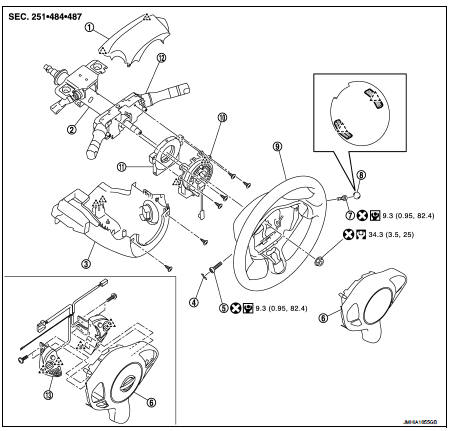
1. Steering column upper cover
2. Steering column assembly
3. Steering column lower cover
4. Side lid LH
5. TORX bolt
6. Driver air bag module
7. TORX bolt
8. Side lid RH
9. Steering wheel
10. Spiral cable
11. Steering angle sensor
12. Combination switch
13. Steering switch
 : Pawl
 : Do not reuse
 : N·m (kg-m, in-lb)
 : N·m (kg-m, ft-lb)
Removal and Installation
WARNING:
• Before servicing, turn ignition switch OFF, disconnect battery negative
terminal and wait 3 minutes
or more.
• Always work from the side of air bag module. Never work in front of it.
• Never use the air tools or electric tools for servicing.
REMOVAL
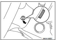
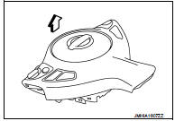
1. Remove side lid (LH and RH).
Insert flat-bladed screwdriver between side lid and steering wheel to disengage pawls as shown in the figure.
: Pawl
2. Remove TORX bolts (LH and RH) from the steering wheel lower side.
3. Pull out driver air bag module.
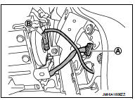
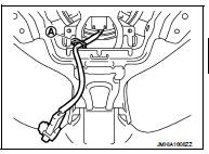
4. Disconnect spiral cable harness connector (A).
5. Disconnect driver air bag harness connector (B).
CAUTION:
• For installing/removing the driver air bag module harness
connector, insert thin screwdriver wrapped in tape into
notch, lift lock and remove the connector.
• Install the connector with lock raised, and push lock into the connector.
• After installing the connector, check that the lock is pushed securely into it.
6. Remove driver air bag module.
CAUTION:
• Always place the driver air bag module with pad side facing
upward.
 : Upward
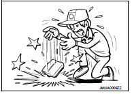
• Never impact the driver air bag module.
• Replace the driver air bag module if it has been dropped or sustained an impact.
• Never insert any foreign objects (screwdriver, etc.) into the driver air bag module.
• Never disassemble the driver air bag module.
• Never expose the driver air bag module to temperatures exceeding 90 °C (194 °F).
• Never allow oil, grease, detergent, or water to come in contact with the driver air bag module.
INSTALLATION
Note the following items, and then install in the reverse order of removal.
CAUTION:
• Never use the old TORX bolts after removal, replace with the new TORX bolts.
• Fix the driver air bag module harnesses to the harness fixing hook (A).
• Never damage the harness while installing.
• Tighten the TORX bolts after completely adjusting the centers of fixing holes on the driver air bag module side and the steering wheel side. If the holes are misaligned, the bolt threads are damaged and the module is not installed securely.
• If malfunction is detected by the air bag warning lamp, after repair or replacement of the malfunctioning parts, reset the memory using self-diagnosis or CONSULT-III. Refer to SRC-12, "On Board Diagnosis Function" or SRC-16, "CONSULT-III Function".
• After the work is complete, check that no system malfunction is detected by air bag warning lamp.

 Spiral cable
Exploded View
1. Steering column upper cover
2. Steering column assembly
3. Steering column lower cover
4. Side lid LH
5. TORX bolt
6. Driver air bag module
7. TORX bolt
8. Side lid RH ...
Other materials:
P0089 fuel pump
DTC Logic
DTC DETECTION LOGIC
NOTE:
• Conditions for applying the diagnostic procedure to the stored DTCs:
The DTC becomes present during the first 30 seconds after the engine starts.
• In low ambient temperature conditions, diagnostic cannot make difference
between a normal long engine
st ...
Fuel level sensor unit
Exploded View
1. Lock ring
2. Fuel level sensor unit
3. Seal packing
A. To fuel tank
: Always replace after every
disassembly
Removal and Installation
WARNING:
Read “General Precautions” when working on the fuel system. Refer to FL-45,
"General Precautions".
REMOVAL
1. Ch ...
Luggage floor trim
Exploded View
2WD models
1. Rear pillar cap RH
2. Luggage side upper finisher RH
3. Luggage side lower finisher RH
4. Luggage floor board
5. Luggage side upper finisher LH
6. Rear pillar cap LH
7. Luggage side lower finisher LH
8. Seat belt hook LH
9. Shock absorber mask LH
10. Lug ...
