Nissan Juke Service and Repair Manual : Drive belt
Exploded View
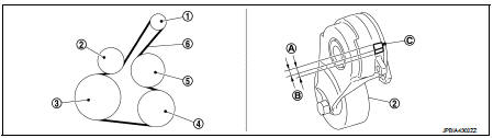
1. Alternator
2. Drive belt auto-tensioner
3. Crankshaft pulley
4. A/C compressor
5. Water pump
6. Drive belt
A. Possible use range B.
Range when new drive belt is installed C. Indicator
Checking
WARNING
: Perform this step when engine is stopped.
• Check that the indicator (C) (notch on fixed side) of drive belt auto-tensioner is within the possible use range (A) in the figure.
NOTE
:
• Check the drive belt auto-tensioner indication when the engine is cold.
• When new drive belt is installed, the indicator (notch on fixed side) should be within the range (B) in the figure.
• Visually check entire drive belt for wear, damage or cracks.
• If the indicator (notch on fixed side) is out of the possible use range or belt is damaged, replace drive belt.
Tension Adjustment
Refer to : EM-129, "Drive Belt".
Removal and Installation
REMOVAL
1. Turn the steering wheel to the right.
2. Remove the front fender protector (RH) front side bolts and clips. And keep a service area. Refer to EXT- 22, "Exploded View".
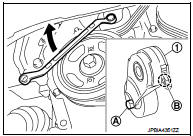
3. Hold the hexagonal part (A) of drive belt auto-tensioner (1) with a wrench securely. Then move the wrench handle in the direction of arrow (loosening direction of tensioner).
CAUTION
:
Avoid placing hand in a location where pinching may occur if the holding tool accidentally comes off
.
4. Insert a rod approximately 6 mm (0.24 in) in diameter such as short-length screwdriver into the hole (B) of the retaining boss to fix drive belt auto-tensioner.
• Keep drive belt auto-tensioner pulley arm locked after drive belt is removed.
5. Remove drive belt.
INSTALLATION
1. Install drive belt.
CAUTION
:
• Confirm drive belt is completely set to pulleys.
• Check for engine oil, working fluid and engine coolant are not adhered to drive belt and each pulley groove
.
2. Release drive belt auto-tensioner, and apply tension to drive belt.
3. Turn crankshaft pulley clockwise several times to equalize tension between each pulley.
4. Confirm tension of drive belt at indicator (notch on fixed side) is within the possible use range. Refer to EM-20, "Exploded View".

 Air cleaner filter
Removal and Installation
REMOVAL
1. Remove air duct assembly (duct side) (1).
2. Unhook the tabs (A) of both ends of the air cleaner cover.
3. Remove the air cleaner filter (1) and air cleaner b ...
Other materials:
P1642 thermoplunger control unit
DTC Logic
DTC DETECTION LOGIC
Diagnosis Procedure
1.CHECK THERMOPLUNGER CONTROL UNIT POWER SUPPLY CIRCUIT
1. Turn ignition switch OFF.
2. Disconnect thermoplunger control unit harness connector.
3. Check the voltage between thermoplunger control unit harness connector and
ground.
Is the ...
Diagnosis system [ABS actuator and electric unit (control
unit)]
CONSULT-III Function
APPLICATION ITEMS
CONSULT-III can display each diagnostic item using the diagnostic test modes
as follows.
*: The following diagnosis information is erased by erasing.
• DTC
• Freeze frame data (FFD)
ECU IDENTIFICATION
ABS actuator and electric unit (control unit) p ...
Power supply and ground circuit
PTC HEATER CONTROL UNIT : Diagnosis Procedure
1.CHECK FUSE
1. Turn ignition switch OFF.
2. Check 10A fuses (No. 3 and 7).
NOTE:
Refer to PG-23, "Fuse and Fusible Link Arrangement".
Is the inspection result normal?
YES >> GO TO 2.
NO >> Replace the blown fuse after ...
