Nissan Juke Service and Repair Manual : Door lock status indicator
Component Function Check
1.CHECK FUNCTION
1. Select “DOOR LOCK” of “BCM” using CONSULT-III.
2. Select “DOOR LOCK IND” in “ACTIVE TEST” mode.
3. Check that the function operates normally according to the following conditions.
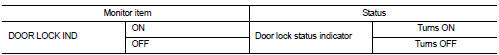
Is the inspection result normal? YES >> Door lock status indicator is OK.
NO >> Refer to DLK-395, "Diagnosis Procedure".
Diagnosis Procedure
1.CHECK DOOR LOCK STATUS INDICATOR INPUT SIGNAL
1. Turn ignition switch OFF.
2. Disconnect door lock status indicator connector.
3. Check voltage between door lock status indicator harness connector and ground.
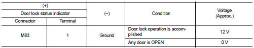
Is the inspection result normal? YES >> GO TO 3.
NO >> GO TO 2.
2.CHECK DOOR LOCK STATUS INDICATOR CIRCUIT
1. Disconnect BCM connector.
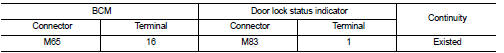
2. Check continuity between BCM harness connector and door lock status indicator harness connector.
3. Check continuity between BCM harness connector and ground.
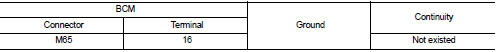
Is the inspection result normal? YES >> Replace BCM. Refer to BCS-161, "Removal and Installation".
NO >> Repair or replace harness.
3.CHECK DOOR LOCK STATUS INDICATOR GROUND
Check continuity between door lock status indicator harness connector and ground.
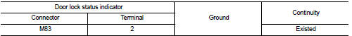
Is the inspection result normal? YES >> Replace door lock status indicator.
NO >> Repair or replace harness.
 Door lock and unlock switch
Driver side
DRIVER SIDE : Component Function Check
1.CHECK FUNCTION
1. Select “DOOR LOCK” of “BCM” using CONSULT-III.
2. Select “CDL LOCK SW”, “CDL UNLOCK SW” in “DATA MONITOR” mode.
3. Check tha ...
 Door switch
Component Function Check
1.CHECK FUNCTION
1. Select “DOOR LOCK” of “BCM” using CONSULT-III.
2. Select “DOOR SW-DR”, “DOOR SW-AS”, “DOOR SW-RL”, “DOOR SW-RR”, “BACK DOOR SW”
in
“DATA MONITOR” mod ...
Other materials:
Oil pan (upper)
Exploded View
1. O-ring
2. Oil pan (upper)
3. Oil level gauge guide
4. O-ring
5. Oil level gauge
6. Oil pump drive chain
7. Crankshaft sprocket
8. Oil pump sprocket
9. Oil pump chain tensioner
10. Oil pump
11. Drain plug
12. Drain plug washer
13. Oil pan (lower)
14. Oil filt ...
Precaution Necessary for Steering Wheel Rotation after Battery Dis
NOTE:
• Before removing and installing any control units, first turn the ignition
switch to the LOCK position, then disconnect
both battery cables.
• After finishing work, confirm that all control unit connectors are connected
properly, then re-connect both
battery cables.
• Always use CONS ...
B2205 vehicle speed
Description
Vehicle speed signal is transmitted from ABS actuator and electric unit
(control unit) via CAN communication
to combination meter.
DTC Logic
DTC DETECTION LOGIC
Diagnosis Procedure
1.PERFORM SELF-DIAGNOSIS OF ABS ACTUATOR AND ELECTRIC UNIT (CONTROL UNIT)
Perform “Self Diagnost ...
