Nissan Juke Service and Repair Manual : Door cable
Exploded View
LEFT SIDE
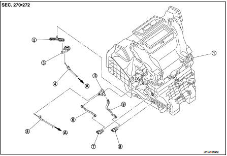
1. A/C unit assembly
2. Intake door lever
3. Intake door link
4. Intake door cable
5. Air mix door cable
6. Upper air mix door rod
7. Upper air mix door lever
8. Lower air mix door lever
9. Lower air mix door rod
10. Air mix door link
A. To A/C control
RIGHT SIDE
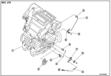
1. A/C unit assembly
2. Main link
3. Sub defroster door link
4. Sub defroster door rod
5. Mode door cable
6. Plate
7. Mode link
8. Sub defroster door lever
9. Center ventilator and defroster door link
10. Plate
11. Center ventilator and defroster door rod
12. Center ventilator and defroster door lever
A. To A/C control
Intake door cable : Removal and Install
REMOVAL
1. Disconnect intake door cable from A/C control. Refer to HAC-239, "Exploded View".
2. Remove instrument lower panel LH. Refer to IP-13, "Removal and Installation".
(LHD models)
3. Remove glove box assembly. Refer to IP-13, "Removal and Installation". (RHD
models)
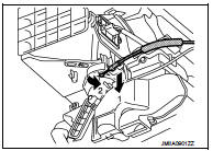
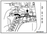
4. Disconnect intake door cable from A/C unit assembly as shown
by the arrow in the figure, and then remove intake door cable.
INSTALLATION
Install in the reverse order of removal.
Mode door cable : Removal and Installation
REMOVAL
1. Disconnect mode door cable from A/C control. Refer to HAC-239, "Exploded View".
2. Remove glove box assembly. Refer to IP-13, "Removal and Installation". (LHD
models)
3. Remove instrument panel RH. Refer to IP-13, "Removal and Installation". (RHD
models)
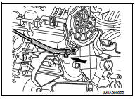
4. Disconnect mode door cable from A/C unit assembly as shown
by the arrow in the figure, and then remove mode door cable.
INSTALLATION
Install in the reverse order of removal.
Air mix door cable : Removal and Installation
REMOVAL
1. Disconnect air mix door cable from A/C control. Refer to HAC-239, "Exploded View".
2. Remove instrument panel LH. Refer to IP-13, "Removal and Installation". (LHD
models)
3. Remove glove box assembly. Refer to IP-13, "Removal and Installation". (RHD
models)
4. Disconnect air mix door cable from A/C unit assembly as shown
by the arrow in the figure, and then remove air mix door cable.
INSTALLATION
Install in the reverse order of removal.
 Blower fan resistor
Exploded View
1. A/C unit assembly
2. Blower fan resistor*1
3. Sub harness*1
4. Power transistor*2
5. Sub harness*2
6. Blower motor
• *1: Manual air conditioner
• *2: Automatic air condi ...

Other materials:
Rear door lock
Exploded View
1. Outside handle assembly
2. Inside handle
3. TORX bolt
4. Door lock assembly
5. Rear door sealing screen
: Clip
: Pawl
: Vehicle front
: Do not reuse
: N·m (kg-m, in-lb)
: Body grease
Door lock
DOOR LOCK : Removal and Installation
REMOVAL
1. Remove rear door glass ...
Evaporative emission system
Inspection
1. Visually inspect EVAP vapor lines for improper attachment and for cracks,
damage, loose connections,
chafing and deterioration.
2. Check EVAP canister as follows:
a. Block port (A). Orally blow air through port (B).
Check that air flows freely through port (C).
b. Block port (B ...
Precaution Necessary for Steering Wheel Rotation after Battery Disconnect
NOTE:
• Before removing and installing any control units, first turn the ignition
switch to the LOCK position, then disconnect
both battery cables.
• After finishing work, confirm that all control unit connectors are connected
properly, then re-connect both
battery cables.
• Always use CONS ...
