Nissan Juke Service and Repair Manual : Direct injection gasoline system
Direct injection gasoline system : System Diagram
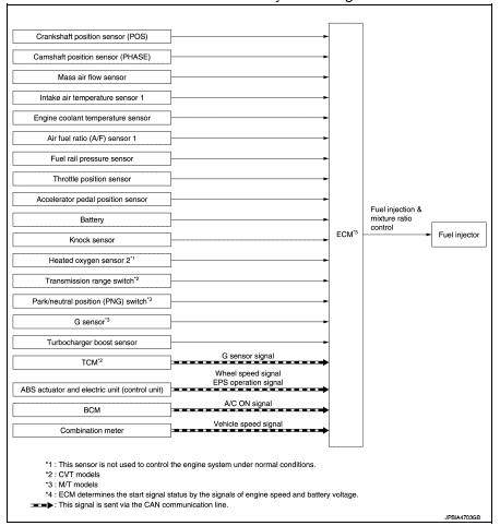
Direct injection gasoline system : System Description
INPUT/OUTPUT SIGNAL CHART
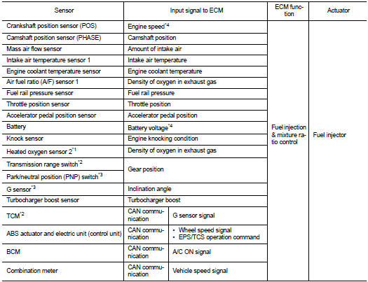
*1: This sensor is not used to control the engine system under normal conditions.
*2: CVT models
*3: M/T models
*4: ECM determines the start signal status by the signals of engine speed and
battery voltage.
SYSTEM DESCRIPTION
The adoption of the direct fuel injection method enables more accurate adjustment of fuel injection quantity by injecting atomized high-pressure fuel directly into the cylinder. This method allows high-powered engine, low fuel consumption, and emissions-reduction.
The amount of fuel injected from the fuel injector is determined by the ECM. The ECM controls the length of time the valve remains open (injection pulse duration). The amount of fuel injected is a program value in the ECM memory. The program value is preset by engine operating conditions. These conditions are determined by input signals (for engine speed, intake air, fuel rail pressure and boost) from the crankshaft position sensor, camshaft position sensor, mass air flow sensor, fuel rail pressure sensor and the turbocharger boost sensor.
VARIOUS FUEL INJECTION INCREASE/DECREASE COMPENSATION
In addition, the amount of fuel injected is compensated to improve engine performance under various operating conditions as listed below.
<Fuel increase>
• During warm-up
• When starting the engine
• During acceleration
• Hot-engine operation
• When selector lever position is changed from N to D (CVT models)
• High-load, high-speed operation
<Fuel decrease>
• During deceleration
• During high engine speed operation
FUEL INJECTION CONTROL
Stratified-charge Combustion Stratified-charge combustion is a combustion method which enables extremely lean combustion by injecting fuel in the latter half of a compression process, collecting combustible air-fuel around the spark plug, and forming fuel-free airspace around the mixture.
Right after a start with the engine cold, the catalyst warm-up is accelerated by stratified-charge combustion.
Homogeneous Combustion Homogeneous combustion is a combustion method that fuel is injected during intake process so that combustion occurs in the entire combustion chamber, as is common with conventional methods.
As for a start except for starts with the engine cold, homogeneous combustion occurs.
MIXTURE RATIO FEEDBACK CONTROL (CLOSED LOOP CONTROL)
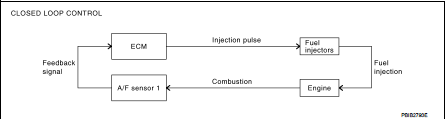
The mixture ratio feedback system provides the best air-fuel mixture ratio for driveability and emission control.
The three way catalyst (manifold) can better reduce CO, HC and NOx emissions. This system uses A/F sensor 1 in the exhaust manifold to monitor whether the engine operation is rich or lean. The ECM adjusts the injection pulse width according to the sensor voltage signal. For more information about A/F sensor 1, refer to EC-39, "Air Fuel Ratio (A/F) Sensor 1". This maintains the mixture ratio within the range of stoichiometric (ideal air-fuel mixture).
This stage is referred to as the closed loop control condition.
Heated oxygen sensor 2 is located downstream of the three way catalyst (manifold). Even if the switching characteristics of A/F sensor 1 shift, the air-fuel ratio is controlled to stoichiometric by the signal from heated oxygen sensor 2.
• Open Loop Control
The open loop system condition refers to when the ECM detects any of the
following conditions. Feedback
control stops in order to maintain stabilized fuel combustion.
- Deceleration and acceleration
- High-load, high-speed operation
- Malfunction of A/F sensor 1 or its circuit
- Insufficient activation of A/F sensor 1 at low engine coolant temperature
- High engine coolant temperature
- During warm-up
- After shifting from N to D (CVT models)
- When starting the engine
MIXTURE RATIO SELF-LEARNING CONTROL
The mixture ratio feedback control system monitors the mixture ratio signal transmitted from A/F sensor 1.
This feedback signal is then sent to the ECM. The ECM controls the basic mixture ratio as close to the theoretical mixture ratio as possible. However, the basic mixture ratio is not necessarily controlled as originally designed. Both manufacturing differences (i.e., mass air flow sensor hot wire) and characteristic changes during operation (i.e., fuel injector clogging) directly affect mixture ratio.
Accordingly, the difference between the basic and theoretical mixture ratios is monitored in this system. This is then computed in terms of “injection pulse duration” to automatically compensate for the difference between the two ratios.
“Fuel trim” refers to the feedback compensation value compared against the basic injection duration. Fuel trim includes “short-term fuel trim” and “long-term fuel trim”.
“Short term fuel trim” is the short-term fuel compensation used to maintain the mixture ratio at its theoretical value. The signal from A/F sensor 1 indicates whether the mixture ratio is RICH or LEAN compared to the theoretical value. The signal then triggers a reduction in fuel volume if the mixture ratio is rich, and an increase in fuel volume if it is lean.
“Long-term fuel trim” is overall fuel compensation carried out over time to compensate for continual deviation of the “short-term fuel trim” from the central value. Continual deviation will occur due to individual engine differences, wear over time and changes in the usage environment.
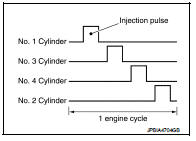
FUEL INJECTION TIMING
Sequential Direct Injection Gasoline System Fuel is injected into each cylinder during each engine cycle according to the ignition order.
STRATIFIED-CHARGE START CONTROL
The use of the stratified-charge combustion method enables emissions-reduction when starting the engine with engine coolant temperature between 5°C (41°F) and 40°C (104°F).
FUEL SHUT-OFF
Fuel to each cylinder is shut-off during deceleration, operation of the engine at excessively high speed or operation of the vehicle at excessively high speed.
 Engine control system
Engine control system : System Diagram
Engine control system : System Description
ECM controls the engine by various functions.
...
 Fuel pressure control
Fuel pressure control : System Diagram
Fuel pressure controlL : System Description
INPUT/OUTPUT SIGNAL CHART
*: ECM determines the start signal status by the engine speed signal and
battery v ...
Other materials:
Precaution for Supplemental Restraint System (SRS) "AIR BAG" and "SEAT BELT
PRE-TENSIONER"
The Supplemental Restraint System such as “AIR BAG” and “SEAT BELT PRE-TENSIONER”,
used along
with a front seat belt, helps to reduce the risk or severity of injury to the
driver and front passenger for certain
types of collision. Information necessary to service the system safely is
include ...
P1832 TCS operation signal
DTC Logic
DTC DETECTION LOGIC
DTC CONFIRMATION PROCEDURE
1.DTC REPRODUCTION PROCEDURE
With CONSULT-III
1. Start the engine and drive at 30 km/h (19 MPH) or more.
2. Perform self-diagnosis for “ALL MODE AWD/4WD”.
Is DTC “P1832” detected?
YES >> Proceed to diagnosis procedure. Refer ...
Power generation voltage variable control system operation
inspection
Inspection Procedure
CAUTION:
When performing this inspection, always use a charged battery that has completed
the battery inspection.
(When the charging rate of the battery is low, the response speed of the voltage
change will
become slow. This can cause an incorrect inspection.)
1.CHECK ...
