Nissan Juke Service and Repair Manual : Diagnosis and repair workflow
Work Flow
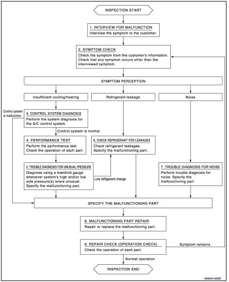
OVERALL SEQUENCE
DETAILED FLOW
1.INTERVIEW FOR MALFUNCTION
Interview the symptom to the customer.
>> GO TO 2.
2.SYMPTOM CHECK
Check the symptom from the customer's information. Check that any symptom occurs other than the interviewed symptom.
Insufficient cooling/heating>>GO TO 3.
Refrigerant leakage>>GO TO 6.
Noise >> GO TO 7.
3.CONTROL SYSTEM DIAGNOSIS
Perform the system diagnosis for the A/C control system.
• Refer to HAC-44, "Work Flow". (AUTOMATIC AIR CONDITIONING: 4WD models) • Refer to HAC-135, "Work Flow". (AUTOMATIC AIR CONDITIONING: 2WD models) • Refer to HAC-216, "Work Flow". (MANUAL AIR CONDITIONING: 4WD models) • Refer to HAC-271, "Work Flow". (MANUAL AIR CONDITIONING: 2WD models)
Is A/C control system normal? YES >> GO TO 4.
NO >> GO TO 8.
4.PERFORMANCE TEST
Perform the performance test. Check the operation of each part. Refer to HA-81, "Inspection".
>> GO TO 5.
5.TROUBLE DIAGNOSIS FOR UNUSUAL PRESSURE
Diagnose using a manifold gauge whenever system's high and/or low side pressure(s) is/are unusual. Specify the malfunctioning part. Refer to HA-83, "Symptom Table".
Low refrigerant charge>>GO TO 6.
Except above>>GO TO 8.
6.CHECK REFRIGERANT FOR LEAKAGES
Check refrigerant for leakages. Specify the malfunctioning part. Refer to HA-74, "Leak Test".
>> GO TO 8.
7.TROUBLE DIAGNOSIS FOR NOISE
Perform trouble diagnosis for noise. Specify the malfunctioning part. Refer to HA-85, "Symptom Table".
>> GO TO 8.
8.MALFUNCTION PART REPAIR
Repair or replace the malfunctioning part.
>> GO TO 9.
9.REPAIR CHECK (OPERATION CHECK)
Check the operation of each part.
Does it operate normally? YES >> INSPECTION END
NO >> GO TO 2.
 Basic inspection
...
 Refrigerant
Description
CONNECTION OF SERVICE TOOLS AND EQUIPMENT
1. Shut-off valve
2. A/C service valve
3. Recovery/recycling/recharging
equipment
4. Vacuum pump
5. Manifold gauge set
6. Refrigeran ...
Other materials:
Shift position indicator circuit
Component Parts Function Inspection
1.CHECK SHIFT POSITION INDICATOR
1. Start the engine.
2. Shift selector lever.
3. Check that the selector lever position and the shift position indicator on
the combination meter are identical.
Is the inspection result normal?
YES >> INSPECTION END ...
How to use the setup button
When the SETUP button is pushed, the Setup screen will appear on the display.
You can select and/or adjust several functions, features and modes that are available
for your vehicle.
Audio setup
Select the “Audio” key to adjust the following items to the preferred setting.
These settings ...
U1117 lost communication (ABS)
Description
CAN (Controller Area Network) is a serial communication line for real-time
application. It is an on-vehicle multiplex
communication line with high data communication speed and excellent malfunction
detection ability.
Many electronic control units are equipped onto a vehicle, and ...
