Nissan Juke Service and Repair Manual : Diagnosis and repair work flow
Work Flow
OVERALL SEQUENCE
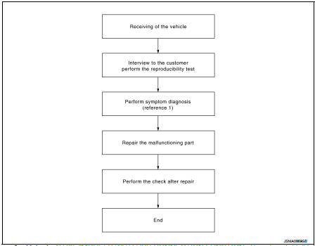
Reference 1··· Refer to AV-33, "MODELS WITH USB CONNECTION FUNCTION : Symptom Table" (with USB connection function) or AV-35, "MODELS WITHOUT USB CONNECTION FUNCTION : Symptom Table" (without USB connection function).
DETAILED FLOW
1.CHECK SYMPTOM
Check the malfunction symptoms by performing the following items.
• Interview the customer to obtain the malfunction information (conditions and environment when the malfunction occurred).
• Check the symptom.
>> GO TO 2.
2.PERFORM DIAGNOSIS BY SYMPTOM
Perform the relevant diagnosis referring to the diagnosis chart by symptom. Refer to AV-33, "MODELS WITH USB CONNECTION FUNCTION : Symptom Table" (with USB connection function) or AV-35, "MODELS WITHOUT USB CONNECTION FUNCTION : Symptom Table" (without USB connection function).
>> GO TO 3.
3.REPAIR OR REPLACE MALFUNCTIONING PARTS
Repair or replace the malfunctioning parts.
>> GO TO 4.
4.FINAL CHECK
Perform the operation to check that the malfunction symptom is solved or any other symptoms are present.
Is there any symptom? YES >> GO TO 2.
NO >> INSPECTION END
 Basic inspection
...
 Additional service when removing battery negative terminal
Description
• The audio unit is equipped with the anti-theft system.
• The audio unit operates after authenticating a fixed four-digit anti-theft
code.
• After removing the battery of the audio u ...
Other materials:
P1585 G sensor
Description
• G sensor is installed to floor under instrument lower cover.
• G sensor detects longitudinal G and inclination that affects the vehicle and
outputs to ECM using analog voltage.
ECM converts the analog voltage value to digital signal and transmits the signal
to TCM via CAN comm ...
P0607 ECM
DTC Logic
DTC DETECTION LOGIC
DTC CONFIRMATION PROCEDURE
1.PERFORM DTC CONFIRMATION PROCEDURE
1. Turn ignition switch ON.
2. Check DTC.
Is DTC detected?
YES >> Proceed to EC-685, "Diagnosis Procedure".
NO >> INSPECTION END
Diagnosis Procedure
1.INSPECTION START
...
System
Relay control system
RELAY CONTROL SYSTEM : System Diagram
*1: Except for MR16DDT engine models
*2: For MR16DDT engine models
RELAY CONTROL SYSTEM : System Description
IPDM E/R activates the internal control circuit to perform the relay ON-OFF
control according to the input signals
from va ...
