Nissan Juke Service and Repair Manual : Diagnosis and repair work flow
Work Flow
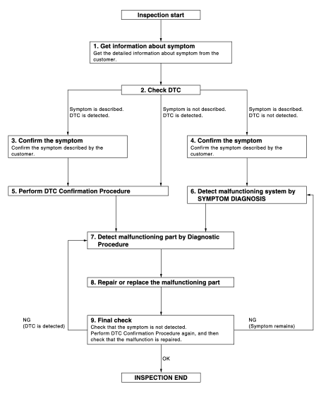
OVERALL SEQUENCE
DETAILED FLOW
1.GET INFORMATION ABOUT SYMPTOM
Get the detailed information from the customer about the symptom (the condition and the environment when the incident/malfunction occurred).
>> GO TO 2.
2.CHECK DTC
1. Check DTC for “ENGINE” and “BCM” using CONSULT-III.
2. Perform the following procedure if DTC is displayed.
- Erase DTC.
- Study the relationship between the cause detected by DTC and the symptom described by the customer.
3. Check related service bulletins for information.
Is any symptom described and any DTC detected? Symptom is described, DTC is displayed>>GO TO 3.
Symptom is described, DTC is not displayed>>GO TO 4.
Symptom is not described, DTC is displayed>>GO TO 5.
3.CONFIRM THE SYMPTOM
Confirm the symptom described by the customer.
Connect CONSULT-III to the vehicle and check self diagnosis results in real time.
Verify relation between the symptom and the condition when the symptom is detected.
>> GO TO 5.
4.CONFIRM THE SYMPTOM
Confirm the symptom described by the customer.
Connect CONSULT-III to the vehicle and check self diagnosis results in real time.
Verify relation between the symptom and the condition when the symptom is detected.
>> GO TO 6.
5.PERFORM DTC CONFIRMATION PROCEDURE
Perform DTC CONFIRMATION PROCEDURE for the displayed DTC, and then check that DTC is detected again.
If two or more DTCs are detected, refer to BCS-140, "DTC Inspection Priority Chart" (BCM) and then determine the trouble diagnosis order.
Is DTC detected? YES >> GO TO 7.
NO >> Refer to GI-42, "Intermittent Incident".
6.DETECT MALFUNCTIONING SYSTEM BY SYMPTOM DIAGNOSIS
Detect malfunctioning system according to SYMPTOM DIAGNOSIS based on the confirmed symptom in step 4, and determine the trouble diagnosis order based on possible causes and symptom.
>> GO TO 7.
7.DETECT MALFUNCTIONING PART BY DIAGNOSTIC PROCEDURE
Inspect according to Diagnostic Procedure of the system.
>> GO TO 8.
8.REPAIR OR REPLACE THE MALFUNCTIONING PART
1. Repair or replace the malfunctioning part.
2. Reconnect parts or connectors disconnected during Diagnostic Procedure again after repair and replacement.
3. Check DTC. If DTC is displayed, erase it.
>> GO TO 9.
9.FINAL CHECK
When DTC was detected in step 2, perform DTC CONFIRMATION PROCEDURE again, and then check that the malfunctions have been fully repaired.
When symptom was described by the customer, refer to the confirmed symptom in step 3 or 4, and check that the symptom is not detected.
Does the symptom reappear? YES (DTC is detected)>>GO TO 7.
YES (Symptom remains)>>GO TO 6.
NO >> INSPECTION END
 Basic inspection
...
 Additional service when replacing control unit
ECM
ECM : Description
Performing the following procedure can automatically activate recommunication
of ECM and BCM, but only
when the ECM is replaced with a new one*.
*: New one means a virgin ...
Other materials:
Antenna
To remove the antenna, hold the bottom of the antenna and turn it counterclockwise.
To install the antenna, turn the antenna clockwise and tighten.
CAUTION
• To avoid damaging or deforming the antenna, be sure to fold down (if so
equipped) or remove the antenna under the following conditions. ...
P1864 input speed signal
DTC Logic
DTC DETECTION LOGIC
DTC CONFIRMATION PROCEDURE
1.PRECONDITIONING
If “DTC CONFIRMATION PROCEDURE” has been previously conducted, always turn
ignition switch OFF and
wait at least 10 seconds before conducting the next test.
>> GO TO 2.
2.DTC REPRODUCTION PROCEDURE
With ...
P245A EGR cooler bypass valve control solenoid valve
DTC Logic
DTC DETECTION LOGIC
NOTE:
If DTC P245A is displayed with DTC P0560 or P0657, first perform trouble
diagnosis for DTC P0560 or P0657.
Refer to EC-963, "DTC Logic" (DTC P0560) or EC-976, "DTC Logic" (DTC P0657).
Diagnosis Procedure
1.CHECK GROUND CONNECTIONS
...
