Nissan Juke Service and Repair Manual : Cylinder block
Exploded View
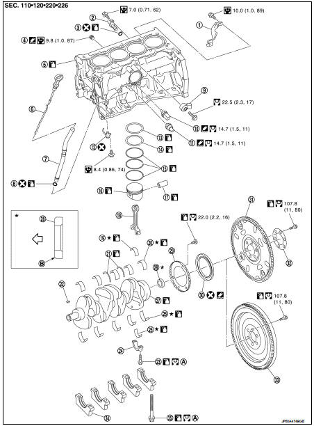
1. Crankshaft position sensor (POS) cover
2. Crankshaft position sensor (POS)
3. O-ring
4. Drain plug
5. Cylinder block
6. Oil level gauge
7. Oil level gauge guide
8. O-ring
9. Knock sensor
10. Oil temperature sensor
11. Oil pressure sensor
12. Oil jet
13. Top ring
14. Second ring
15. Oil ring
16. Piston
17. Piston pin
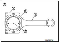
18. Connecting rod
19. Connecting rod bearing (upper)
20. Main bearing (upper)
21. Thrust bearing
22. Crankshaft key
23. Connecting rod bolt
24. Connecting rod cap
25. Connecting rod bearing (lower)
26. Main bearing (lower)
27. Crankshaft
28. Pilot converter (CVT models)
29. Signal plate
30. Rear oil seal
31. Drive plate
32. Rein force plate
33. Fly wheel (M/T models)
34. Main bearing cap bolt
A.Tightening must be done following the assembly procedure.
Refer to EM-228
B. Chamfered
 : Crankshaft side
 : Always replace after every
disassembly.
 : N·m (kg-m, in-lb)
 : N·m (kg-m, ft-lb)
 : Sealing point
 : Should be lubricated with oil.
 : Select with proper thickness.
Disassembly and Assembly
DISASSEMBLY
NOTE
:
Explained here is how to disassemble with an engine stand supporting mating
surface of transaxle. When
using different type of engine stand, note with difference in steps and etc.
1. Remove cylinder head. Refer to EM-208, "Exploded View".
2. Remove knock sensor.
CAUTION:
Carefully handle knock sensor avoiding shocks.
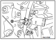
3. Remove cover, and then crankshaft position sensor (POS).
1. O ring
2. Crank shaft position sensor (POS)
3. Cover
 : Engine front
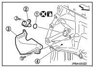
CAUTION:
• Avoid impacts such as a dropping.
• Never disassemble.
• Keep it away from metal particles.
• Never place the sensor in a location where it is exposed to magnetism.
4. Remove oil pan (upper and lower). Refer to EM-222, "Exploded View".
5. Remove piston and connecting rod assembly with the following procedure: • Before removing piston and connecting rod assembly, check the connecting rod side clearance. Refer to EM-236, "Inspection".
a. Position crankshaft pin corresponding to connecting rod to be removed onto the bottom dead center.
b. Remove connecting rod cap.
c. Using a hammer handle or similar tool, push piston and connecting rod assembly out to the cylinder head side.
CAUTION:
• Be careful not to damage matching surface with connecting
rod cap.
• Be careful not to damage the cylinder wall and crankshaft pin, resulting from an interference of the connecting rod big end.
6. Remove connecting rod bearings.
CAUTION:
Identify installation positions, and store them without mixing them up.
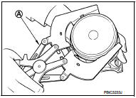
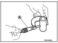
7. Remove piston rings form piston.
• Before removing piston rings, check the piston ring side clearance. Refer to EM-236, "Inspection".
• Use a piston ring expander (commercial service tool) (A).
CAUTION:
• When removing piston rings, be careful not to damage
the piston.
• Be careful not to damage piston rings by expanding them excessively.
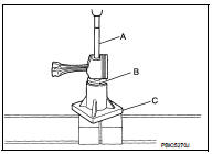
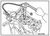
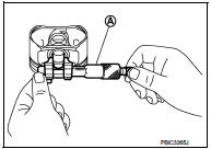
8. Remove piston from connecting rod.
• Use a piston pin press stand (SST) and a press to remove the piston pin.
• For the details of SST, refer to the following.
A : Drift [KV10109730] B : Center cap [KV10110310] C : Press stand [ST13030020]
CAUTION:
Be careful not to damage the piston and connecting rod.
NOTE:
The joint between the connecting rod and the piston pin is a press fit.
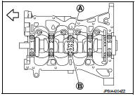
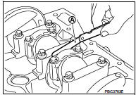
9. Remove the main bearing cap in the following procedure.
• Measure crankshaft end play before loosening main bearing cap bolts. Refer to EM-236, "Inspection".
a. Loosen and remove bolts in several steps in reverse of the numerical order as shown in the figure.
 : Engine front
• TORX socket (size: E14) can be used.
b. Remove the main bearing cap from the cylinder block while tapping lightly with a plastic hammer.
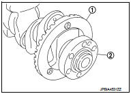
10. Remove crankshaft (2).
CAUTION:
• Be careful not damage or deform signal plate (1) mounted
on crankshaft.
• When setting crankshaft on a flat floor surface, use a block of wood to avoid interference between signal plate and the floor surface.
• Never remove signal plate unless it is necessary to do so.
NOTE
:
When removing or installing signal plate, use TORX socket (size
T40).
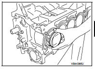
11. Pull rear oil seal out from rear end of crankshaft.
12. Remove main bearing (upper and lower) and thrust bearings from cylinder block and main bearing cap.
CAUTION:
Identify installation positions, and store them without mixing them up.
13. Remove oil jets.
CAUTION:
Insert the dowel pin of oil jet into the cylinder block dowel pin hole to loosen
the mounting bolt.
ASSEMBLY
1. Fully air-blow engine coolant and engine oil passages in cylinder block, cylinder bore and crankcase to remove any foreign material.
CAUTION:
Use a goggles to protect your eye.
2. Install oil jets.
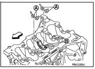
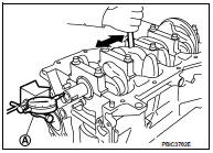
3. Install main bearings and thrust bearings with the following procedure: a. Remove dust, dirt, and engine oil on the bearing mating surfaces of cylinder block.
b. Install thrust bearings to the both sides of the No. 3 journal housing (B) on cylinder block.
 : Engine front
• Install thrust bearings with the oil groove (A) facing crankshaft arm (outside).
c. Install the main bearings (1) paying attention to the direction.
• Install the one with oil holes (A) onto cylinder block and the one without oil holes onto main bearing cap.
• Before installing main bearings, apply new engine oil to the bearing surface (inside). Do not apply engine oil to the back surface, but thoroughly clean it.
• Ensure the oil holes on cylinder block and those on the corresponding bearing are aligned.
• Install the main bearing in the position as shown in the figure.
1 : Cylinder block
2 : Main bearing (upper)
3 : Main bearing (lower)
4 : Main bearing cap
: Engine front
NOTE
:
Install the main bearing in the center position with the following
dimension. For service operation, the center position can be
checked visually.
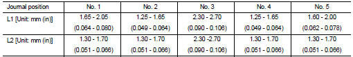
CAUTION:
Dimension L1 of journal No. 3 is the distance from the housing base end surface
(bulk) (it is not
the distance from the thrust bearing mounting end surface).
4. Install signal plate to crankshaft if removed.
a. Set the signal plate (1) with the flange facing toward the counterweight side (engine front side) to the crankshaft rear surface.
A : Dowel pin hole
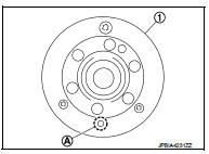
b. After positioning crankshaft and signal plate with positioning dowel pin, tighten bolt.
NOTE
:
Dowel pin of crankshaft and signal plate is provided as a set for
each.
c. Remove dowel pin.
CAUTION:
Be sure to remove dowel pin.
5. Install crankshaft to cylinder block.
• While turning crankshaft by hand, check that it turns smoothly.
CAUTION:
Never install rear oil seal yet.
6. Install main bearing caps.
• Install the main bearing cap while referring to the front mark (B) and the journal number stamp (A).
 : Engine front
NOTE
:
Main bearing cap cannot be replaced as a single parts,
because it is machined together with cylinder block.
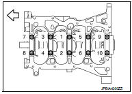
7. Tighten main bearing cap bolts in numerical order as shown in the figure with the following steps.
: Engine front
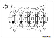
a. Apply new engine oil to threads and seat surfaces of the mounting bolts.
b. Tighten main bearing cap bolts.
: 32.4 N·m (3.3 kg-m, 24 ft-lb)
c. Turn main bearing cap bolts 60 degrees clockwise (angle tightening) in numerical order as shown in the figure.
CAUTION:
Check and confirm the tightening angle by using the angle
wrench [SST: KV10112100] (A) or protractor. Avoid judgment
by visual inspection without the tool.
• After installing the mounting bolts, check that crankshaft can be rotated smoothly by hand.
• Check crankshaft end play. Refer to EM-236, "Inspection".
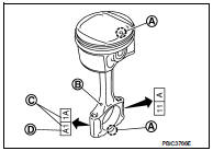
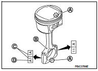
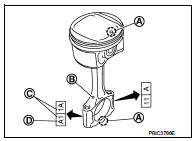
8. Install piston to connecting rod with the following procedure: a. Set so that the front mark (A) on the piston head and the cylinder number (C) are in the position as shown in the figure.
B : Oil hole
D : Connecting rod big end grade
NOTE
:
The symbols without notes are for management
b. Press-fit the piston pin using the piston pin press stand (SST).
• For the details of SST, refer to the following.
A : Drift [KV10109730]
B : Center cap [KV10110310]
C : Press stand [ST13030020]
D : Center shaft KV10114120]
E : Spring [ST13030030]
F : Detail
CAUTION:
Press-fit the piston so as not to damage it.
NOTE:
The joint between the connecting rod and the piston pin is a press fit.
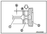
• Press-fit the piston pin (2) from piston surface (A) to the depth of 2.35 mm (0.092 in) (b).
1 : Connecting rod : Press-fit direction
• After finishing work, check that the piston (3) moves freely.
9. Using a piston ring expander (commercial service tool), install piston rings.
CAUTION:
• Be careful not to damage piston.
• Be careful not to damage piston rings by expanding them excessively.
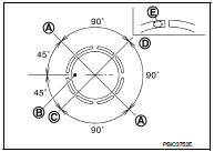
• Position each ring with the gap as shown in the figure referring to the piston front mark (B).
A : Oil ring upper or lower rail gap (either of them) C : Second ring and oil ring spacer gap D : Top ring gap
• Install second ring with the stamped mark (E) facing upward.
Stamped mark:
Top ring : 1R
Second ring : 2R
10. Install connecting rod bearings to connecting rod and connecting rod cap.
• When installing connecting rod bearings, apply new engine oil to the bearing surface (inside). Do not apply engine oil to the back surface, but thoroughly clean it.
• Install the bearing in the center position.
NOTE
:
There is no stopper tab.
• Check that the oil holes on connecting rod and connecting rod bearing are aligned.
• Install the connecting rod in the dimension as shown in the figure.
1 : Connecting rod
2 : Connecting rod bearing (upper)
3 : Connecting rod bearing (lower)
4 : Connecting rod cap
A : 1.7 - 2.1 mm (0.067 - 0.083 in)
 : Engine front
NOTE
:
Install the connecting rod bearing in the center position with
the dimension as shown in the figure. For service operation, the center position
can be checked visually.
11. Install piston and connecting rod assembly to crankshaft.
• Position crankshaft pin corresponding to connecting rod to be installed onto the bottom dead center.
• Apply new engine oil sufficiently to the cylinder bore, piston and crankshaft pin.
• Match the cylinder position with the cylinder number on connecting rod to install.
• Using the piston ring compressor [SST: EM03470000] (A) or suitable tool, install piston with the front mark on the piston head facing the front of the engine.
CAUTION:
• Be careful not to damage matching surface with connecting
rod cap.
• Be careful not to damage the cylinder wall and crankshaft pin, resulting from an interference of the connecting rod big end.
12. Install connecting rod cap.
• Match the stamped cylinder number marks (C) on connecting rod with those on connecting rod cap to install.
A : Front mark
B : Oil hole
D : Connecting rod big end grade
13. Inspect outer diameter of connecting rod bolts. Refer to EM-236, "Inspection".
14. Tighten connecting rod bolt with the following procedure: a. Apply new engine oil to the threads and seats of connecting rod bolts.
b. Tighten bolts in several steps.
 : 27.4 N·m (2.8 kg-m, 20 ft-lb)
c. Completely loosen bolts.
 : 0 N·m (0 kg-m, 0 ft-lb)
d. Tighten bolts in several steps.
 : 19.6 N·m (2.0 kg-m, 14 ft-lb)
• Check that the oil holes on connecting rod and connecting rod bearing are aligned.
• Install the connecting rod in the dimension as shown in the figure.
1 : Connecting rod
2 : Connecting rod bearing (upper)
3 : Connecting rod bearing (lower)
4 : Connecting rod cap
A : 1.7 - 2.1 mm (0.067 - 0.083 in)
: Engine front
NOTE
:
Install the connecting rod bearing in the center position with
the dimension as shown in the figure. For service operation, the center position
can be checked visually.
11. Install piston and connecting rod assembly to crankshaft.
• Position crankshaft pin corresponding to connecting rod to be installed onto the bottom dead center.
• Apply new engine oil sufficiently to the cylinder bore, piston and crankshaft pin.
• Match the cylinder position with the cylinder number on connecting rod to install.
• Using the piston ring compressor [SST: EM03470000] (A) or suitable tool, install piston with the front mark on the piston head facing the front of the engine.
CAUTION:
• Be careful not to damage matching surface with connecting
rod cap.
• Be careful not to damage the cylinder wall and crankshaft pin, resulting from an interference of the connecting rod big end.
12. Install connecting rod cap.
• Match the stamped cylinder number marks (C) on connecting rod with those on connecting rod cap to install.
A : Front mark
B : Oil hole
D : Connecting rod big end grade
13. Inspect outer diameter of connecting rod bolts. Refer to EM-236, "Inspection".
14. Tighten connecting rod bolt with the following procedure: a. Apply new engine oil to the threads and seats of connecting rod bolts.
b. Tighten bolts in several steps.
 : 27.4 N·m (2.8 kg-m, 20 ft-lb)
c. Completely loosen bolts.
 : 0 N·m (0 kg-m, 0 ft-lb)
d. Tighten bolts in several steps.
 : 19.6 N·m (2.0 kg-m, 14 ft-lb)
e. Then turn all bolts 60 degrees clockwise (angle tightening).
CAUTION:
Check and confirm the tightening angle by using the angle
wrench [SST: KV10112100] (A) or protractor. Avoid judgement
by visual inspection without the tool.
• After tightening connecting rod bolt, check that crankshaft rotates smoothly.
• Check the connecting rod side clearance. Refer to EM-236, "Inspection".
15. Install oil pan (upper). Refer to EM-222, "Exploded View".
NOTE
:
Install the rear oil seal after installing the oil pan (upper).
16. Install rear oil seal. Refer to EM-206, "REAR OIL SEAL : Removal and Installation".
17. Install flywheel and drive plate.
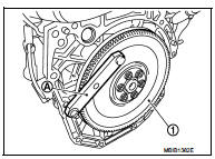
M/T models
• Secure flywheel (1) with a stopper plate [SST: KV11105210]
(A), and remove mounting bolts.
• Using TORX socket (size E20), loosen mounting bolts.
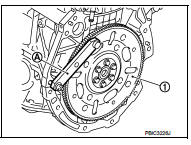
CVT models
• Secure drive plate (1) with a stopper plate [SST: KV11105210]
(A), and remove mounting bolts.
• Using TORX socket (size E20), loosen mounting bolts.
CAUTION:
Be careful not to damage or scratch and contact surface for clutch disc of
flywheel.
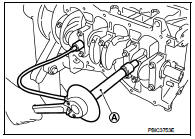
18. Install knock sensor (1).
 : Engine front
• Install connectors so that they are positioned towards the rear of the engine.
CAUTION:
• Never tighten mounting bolt while holding the connector.
• If any impact by dropping is applied to knock sensor, replace it with a new one.
NOTE:
• Check that there is no foreign material on the cylinder block mating surface and the back surface of knock sensor.
• Check that knock sensor does not interfere with other parts.
19. Install crankshaft position sensor (POS).
• Tighten bolts with it seated completely.
20. For the oil level gauge guide (1), fix the position (B) shown in the figure to the water inlet clip (A) after inserting to the cylinder block side.
21. Assemble in the reverse order of disassembly after this step.
Inspection
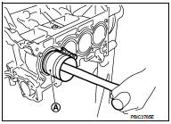
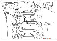
CRANKSHAFT END PLAY
• Measure the clearance between thrust bearings and crankshaft arm when crankshaft is moved fully forward or backward with a dial indicator (A).
Standard and Limit : Refer to EM-255, "Cylinder Block".
• If the measured value exceeds the limit, replace thrust bearings, and measure again. If it still exceeds the limit, replace crankshaft also.
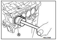
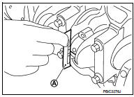
CONNECTING ROD SIDE CLEARANCE
• Measure the side clearance between connecting rod and crankshaft arm with a feeler gauge (A).
Standard and Limit : Refer to EM-255, "Cylinder Block".
• If the measured value exceeds the limit, replace connecting rod, and measure again. If it still exceeds the limit, replace crankshaft also.
PISTON TO PISTON PIN OIL CLEARANCE
Piston Pin Hole Diameter Measure the inner diameter of piston pin hole with an inside micrometer (A).
Standard : Refer to EM-255, "Cylinder Block".
Piston Pin Outer Diameter Measure the outer diameter of piston pin with a micrometer (A).
Standard : Refer to EM-255, "Cylinder Block".
Piston to Piston Pin Oil Clearance (Piston to piston pin oil clearance) = (Piston pin hole diameter) – (Piston pin outer diameter)
Standard : Refer to EM-255, "Cylinder Block".
• If oil clearance is out of the standard, replace piston and piston pin assembly.
• When replacing piston and piston pin assembly. Refer to ″″.
NOTE:
• Piston is available together with piston pin as assembly.
• Piston pin (piston pin hole) grade is provided only for th
PISTON RING SIDE CLEARANCE
• Measure the side clearance of piston ring and piston ring groove with a feeler gauge (A).
Standard and Limit : Refer to EM-255, "Cylinder Block".
• If the measured value exceeds the limit, replace piston ring, and measure again. If it still exceeds the limit, replace piston also.
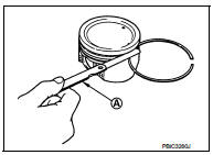
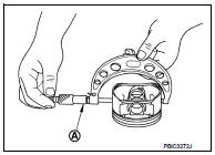
PISTON RING END GAP
• Check that cylinder bore inner diameter is within specification. Refer to “PISTON TO CYLINDER BORE CLEARANCE”.
• Lubricate with new engine oil to piston (1) and piston ring (2), and then insert (A) piston ring until middle of cylinder (B) with piston, and measure piston ring end gap with a feeler gauge (C).
Standard and Limit : Refer to EM-255, "Cylinder Block".
• If the measured value exceeds the limit, replace piston ring, and measure again. If it still exceeds the limit, replace cylinder block.
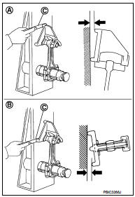
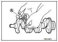
CONNECTING ROD BEND AND TORSION
• Check with a connecting rod aligner.
A : Bend
B : Torsion
C : Feeler gauge
Limit : Refer to EM-255, "Cylinder Block".
• If it exceeds the limit, replace connecting rod assembly
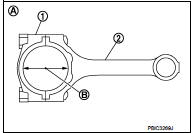
CONNECTING ROD BIG END DIAMETER
• Install connecting rod cap (1) without connecting rod bearing installed, and tightening connecting rod cap bolts to the specified torque. Refer to EM-227, "Exploded View".
2 : Connecting rod
A : Example
B : Measuring direction of inner diameter
• Measure the inner diameter of connecting rod big end with an inside micrometer.
Standard : Refer to EM-255, "Cylinder Block".
• If out of the standard, replace connecting rod assembly.
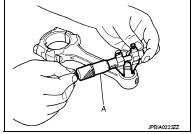
CONNECTING ROD BUSHING OIL CLEARANCE
Connecting Rod Bushing Inner Diameter Measure the inner diameter of connecting rod bushing with an inside micrometer (A).
Standard : Refer to EM-255, "Cylinder Block".
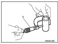
Piston Pin Outer Diameter Measure the outer diameter of piston pin with a micrometer (A).
Standard : Refer to EM-255, "Cylinder Block".
Connecting Rod Bushing Oil Clearance (Connecting rod bushing oil clearance) = (Connecting rod bushing inner diameter) – (Piston pin outer diameter)
Standard and Limit : Refer to EM-255, "Cylinder Block".
• If the measured value is out of the standard, replace connecting rod assembly and/or piston and piston pin assembly.
• If replacing piston and piston pin assembly. Refer to EM-255, "Cylinder Block".
• If replacing connecting rod assembly. Refer to EM-258, "Connecting Rod Bearing".
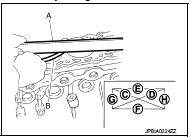
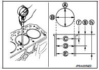
CYLINDER BLOCK TOP SURFACE DISTORTION
• Using a scraper, remove gasket on the cylinder block surface, and also remove engine oil, scale, carbon, or other contamination.
CAUTION:
Be careful not to allow gasket flakes to enter engine oil or engine coolant
passages.
• Measure the distortion on the cylinder block upper face at some different points in six directions with a straight edge (A) and feeler gauge (B).
Limit : Refer to EM-255, "Cylinder Block".
• If it exceeds the limit, replace cylinder block.
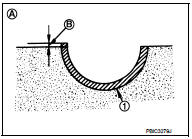
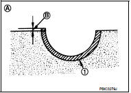
MAIN BEARING HOUSING INNER DIAMETER
• Install main bearing cap without main bearings installed, and tighten main bearing cap mounting bolts to the specified torque. Refer to EM-228, "Disassembly and Assembly".
• Measure the inner diameter of main bearing housing with a bore gauge.
• Measure the position shown in the figure [5 mm (0.20 in)] backward from main bearing housing front side in the 2 directions as shown in the figure. The smaller one is the measured value.
1 : Cylinder block
2 : Main bearing cap
 : Engine front
Standard : Refer to EM-255, "Cylinder Block".
• If out of the standard, replace cylinder block and main bearing caps assembly.
NOTE
:
Main bearing caps cannot be replaced as a single, because it is machined
together with cylinder block.
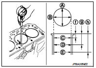
PISTON TO CYLINDER BORE CLEARANCE
Cylinder Bore Inner Diameter • Using a bore gauge, measure the cylinder bore for wear, out-ofround and taper at six different points on each cylinder. [(A) and (B) directions at (C), (D), and (E)] [(A) is in longitudinal direction of engine]
f : 10 mm (0.39 in)
g : 60 mm (2.36 in)
h : 124 mm (4.88 in)
NOTE
:
When determining cylinder bore grade, measure the cylinder bore
(B) direction at (D) position.
Standard:
Cylinder bore inner diameter
: Refer to EM-255, "Cylinder Block".
Limit:
Out-of-round [Difference between (A) and (B)]
Taper [Difference between (C) and (D)]
: Refer to EM-255, "Cylinder Block".
• If the measured value exceeds the limit, or if there are scratches and/or seizure on the cylinder inner wall, replace cylinder block.
NOTE
:
Oversize piston is not provided.
Piston Skirt Diameter Measure the outer diameter of piston skirt with a micrometer (A).
Standard : Refer to EM-255, "Cylinder Block".
Piston to Cylinder Bore Clearance Calculate by piston skirt diameter and cylinder bore inner diameter [direction (B), position (D)].
A : Direction A
C : Position C
E : Position E
f : 10 mm (0.39 in)
g : 60 mm (2.36 in)
h : 124 mm (4.88 in)
(Clearance) = (Cylinder bore inner diameter) – (Piston skirt diameter)
Standard and Limit : Refer to EM-255, "Cylinder Block".
• If it exceeds the limit, replace piston and piston pin assembly and/or cylinder block. Refer to EM-255, "Cylinder Block".
CRANKSHAFT MAIN JOURNAL DIAMETER
• Measure the outer diameter of crankshaft main journals with a micrometer (A).
Standard : Refer to EM-255, "Cylinder Block".
• If out of the standard, measure the main bearing oil clearance.
Then use undersize bearing. Refer to EM-257, "Main Bearing".
CRANKSHAFT PIN JOURNAL DIAMETER
• Measure the outer diameter of crankshaft pin journal with a micrometer.
Standard : Refer to EM-255, "Cylinder Block".
• If out of the standard, measure the connecting rod bearing oil clearance. Then use undersize bearing. Refer to EM-258, "Connecting Rod Bearing".
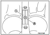
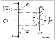
OUT-OF-ROUND AND TAPER OF CRANKSHAFT
• Measure the dimensions at four different points as shown in the figure on each main journal and pin journal with a micrometer.
• Out-of-round is indicated by the difference in dimensions between (a) and (b) at (c) and (d).
• Taper is indicated by the difference in dimension between (c) and (d) at (a) and (b).
Limit:
Out-of-round [Difference between (a) and (b)]
Taper [Difference between (c) and (d)]
: Refer to EM-255, "Cylinder Block".
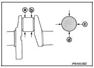
• If the measured value exceeds the limit, correct or replace crankshaft.
• If corrected, measure the bearing oil clearance of the corrected main journal and/or pin journal. Then select main bearing and/or connecting rod bearing. Refer to EM-258, "Connecting Rod Bearing" and/or EM-257, "Main Bearing".
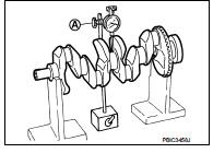
CRANKSHAFT RUNOUT
• Place a V-block on a precise flat table to support the journals on the both end of the crankshaft.
• Place a dial indicator (A) straight up on the No. 3 journal.
• While rotating crankshaft, read the movement of the pointer on the dial indicator. (Total indicator reading)
Standard and Limit : Refer to EM-255, "Cylinder Block".
• If it exceeds the limit, replace crankshaft.
CONNECTING ROD BEARING OIL CLEARANCE
Method by Calculation • Install connecting rod bearings (2) to connecting rod (3) and connecting rod bearing cap (1), and tighten connecting rod cap bolts to the specified torque. Refer to EM-228, "Disassembly and Assembly".
A : Example
B : Inner diameter measuring direction
• Measure the inner diameter of connecting rod bearing with an inside micrometer.
(Bearing oil clearance) = (Connecting rod bearing inner diameter) – (Crankshaft pin journal diameter)
Standard and Limit : Refer to EM-258, "Connecting Rod Bearing".
• If clearance exceeds the limit, select proper connecting rod bearing according to connecting rod big end diameter and crankshaft pin journal diameter to obtain specified bearing oil clearance. Refer to EM-258, "Connecting Rod Bearing".
Method of Using Plastigage • Remove engine oil and dust on crankshaft pin and the surfaces of each bearing completely.
• Cut a plastigage slightly shorter than the bearing width, and place it in crankshaft axial direction, avoiding oil holes.
• Install connecting rod bearings to connecting rod and cap, and tighten connecting rod cap bolts to the specified torque. Refer to EM-228, "Disassembly and Assembly".
CAUTION:
Never rotate crankshaft.
• Remove connecting rod cap and bearing, and using the scale (A) on the plastigage bag, measure the plastigage width.
NOTE
:
The procedure when the measured value exceeds the limit is
same as that described in the “Method by Calculation”.
MAIN BEARING OIL CLEARANCE
Method by Calculation • Install main bearings (3) to cylinder block (1) and main bearing cap (2), and tighten main bearing cap mounting bolts to the specified torque. Refer to EM-228, "Disassembly and Assembly".
A : Example
B : Inner diameter measuring direction
• Measure the inner diameter of main bearing with a bore gauge.
(Bearing oil clearance) = (Main bearing inner diameter) – (Crankshaft main journal diameter)
Standard and Limit : Refer to EM-257, "Main Bearing".
• If clearance exceeds the limit, select proper main bearing according to main bearing inner diameter and crankshaft main journal diameter to obtain specified bearing oil clearance. Refer to EM-257, "Main Bearing".
Method of Using Plastigage • Remove engine oil and dust on crankshaft main journal and the surfaces of each bearing completely.
• Cut a plastigage slightly shorter than the bearing width, and place it in crankshaft axial direction, avoiding oil holes.
• Install main bearings to cylinder block and main bearing cap, and tighten main bearing cap mounting bolts to the specified torque. Refer to EM-228, "Disassembly and Assembly".
CAUTION:
Never rotate crankshaft.
• Remove main bearing cap and bearings, and using the scale (A) on the plastigage bag, measure the plastigage width.
NOTE
:
The procedure when the measured value exceeds the limit is
same as that described in the “Method by Calculation”.
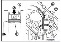
MAIN BEARING CRUSH HEIGHT
• When main bearing cap is removed after being tightened to the specified torque with main bearings (1) installed, the tip end of bearing must protrude (B). Refer to EM-228, "Disassembly and Assembly".
A : Example
Standard : There must be crush height.
• If the standard is not met, replace main bearings.
CONNECTING ROD BEARING CRUSH HEIGHT
• When connecting rod cap is removed after being tightened to the specified torque with connecting rod bearings (1) installed, the tip end of bearing must protrude (B). Refer to EM-228, "Disassembly and Assembly".
A : Example
Standard : There must be crush height.
• If the standard is not met, replace connecting rod bearings.
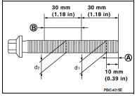
MAIN BEARING CAP BOLT OUTER DIAMETER
• Measure the outer diameters (d1) and (d2) at two positions as shown in the figure.
A : (d1) measuring position B : (d2) measuring position
• If reduction appears in places other than (B) range, regard it as (d2).
Limit [(d1) – (d2)]: 0.15 mm (0.0059 in)
• If it exceeds the limit (a large difference in dimensions), replace main bearing cap mounting bolt with a new one.
CONNECTING ROD CAP BOLT OUTER DIAMETER
• Measure the outer diameter (d) at position as shown in the figure.
• If reduction appears in a position other than (d), regard it as (d).
Limit: 7.75 mm (0.3051 in)
• When (d) exceeds the limit (when it becomes thinner), replace connecting rod cap bolt with a new one.
CLOGGED OR DAMAGED OIL FILTER (FOR INTAKE VALVE TIMING CONTROL)
• Check that there is no foreign material on the oil filter and check it for clogging.
- Clean it if necessary.
• Check the oil filter for damage.
- Replace it if necessary.
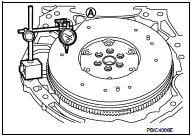
FLYWHEEL DEFLECTION (M/T models)
• Measure the deflection of flywheel contact surface to torque with a dial indicator (A).
• Measure the deflection at 210 mm (8.27 in) diameter.
Limit : 0.45 mm (0.0177 in) or less.
• If measured value is out of the standard, replace flywheel.
• If a trace of burn or discoloration is found on the surface, repair it with sandpaper.
CAUTION:
When measuring, keep magnetic fields (such as dial indicator
stand) away from signal plate of the rear end of crankshaft.
MOVEMENT AMOUNT OF FLYWHEEL (M/T models)
CAUTION:
Never disassemble double mass flywheel.
Movement Amount of Thrust (Fore-and-Aft) Direction • Measure the movement amount of thrust (fore-and-aft) direction when 100 N (10.2 kg, 22 lb) force is added at the portion of 125 mm (4.92 in) radius from the center of flywheel.
Standard : 1.8 mm (0.071 in) or less
• If measured value is out of the standard, replace flywheel.
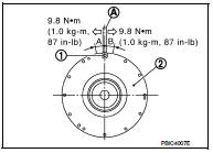
Movement Amount in Radial (Rotation) Direction Check the movement amount of radial (rotation) direction with the following procedure: 1. Install clutch cover mounting bolt (1) to clutch cover mounting hole, and place a torque wrench (A) on the extended line of the flywheel (2) center line.
• Tighten bolt at a force of 9.8 N·m (1.0 kg-m, 87 in-lb) to keep it from loosening.
2. Put a matching mark on circumferences of the two flywheel masses without applying any load (Measurement standard points).
3. Apply a force of 9.8 N·m (1.0 kg-m, 87 in-lb) in each direction, and mark the movement amount on the mass on the transaxle side.
4. Measure the dimensions of movement amounts “A” and “B” on circumference of the flywheel on the transaxle side.
Limit : 33.2 mm (1.307 in) or less.
• If measured value is out of the standard, replace flywheel.
 Oil pan (upper)
Exploded View
With Oil Cooler
1. Rear oil seal
2. O-ring
3. Oil pan (upper)
4. Oil pump chain tensioner (for oil
pump drive chain)
5. Oil pump drive chain
6. Crankshaft sprocket
7. Oil p ...
 How to select piston and bearing
Description
• The identification grade stamped on each part is the grade for the
dimension measured in new condition. This grade cannot apply to reused parts.
• For reused or repaired parts, mea ...
Other materials:
Hazard function
Component Function Check
1.CHECK FUNCTION
1. Select “INTELLIGENT KEY” of “BCM” using CONSULT-III.
2. Select “FLASHER” in “ACTIVE TEST” mode.
3. Check that the function operates normally according to the following
conditions.
Is the inspection result normal?
YES >> Hazard warning lamp ...
P0011 IVT control
DTC Logic
DTC DETECTION LOGIC
NOTE:
If DTC P0011 is displayed with DTC P0075, first perform the trouble diagnosis
for EC-307, "DTC Logic".
DTC CONFIRMATION PROCEDURE
1.PRECONDITIONING
If DTC Confirmation Procedure has been previously conducted, always perform
the following proc ...
Turbocharger
Exploded View
1. Heat insulator
2. Actuator hose
3. Clamp
4. Turbocharger inlet tube
5. Gasket
6. Gasket
7. Clamp
8. Oil outlet hose
9. Oil return pipe
10. Oil supply tube
11. O-ring
12. O-ring
13. Turbocharger
14. Eye bolt
15. Gasket
16. Oil supply tube
A. To EVAP canis ...
