Nissan Juke Service and Repair Manual : CVT fluid
Replacement
CVT fluid : Refer to TM-512, "General Specification".
Fluid capacity : Refer to TM-512, "General Specificatio
CAUTION
:
• Use only Genuine NISSAN CVT Fluid NS-2. Using transmission fluid other than
Genuine NISSAN
CVT Fluid NS-2 will damage the CVT, which is not covered by the (NISSAN new
vehicle limited) warranty.
• Always use shop paper. Never use shop cloth.
• Replace a drain plug gasket with new ones at the final stage of the operation when installing.
• Use caution when looking into the drain hole as there is a risk of dripping fluid entering the eye.
• After replacement, always perform CVT fluid leakage check.
1. Select “Data Monitor” in “TRANSMISSION” using CONSULT-III.
2. Select “FLUID TEMP” and confirm that the CVT fluid temperature is 40°C (104°F) or less.
3. Check that the selector lever is in the “P” position, then completely engage the parking brake.
4. Lift up the vehicle.
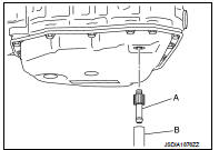
5. Remove the drain plug and overflow tube and drain the CVT fluid from the oil pan. TM-493, "Exploded View".
6. Install the charging pipe set (KV311039S0) (A) into the drain hole.
CAUTION:
Tighten the charging pipe by hand.
7. Install the ATF changer hose (B) to the charging pipe.
CAUTION:
Press the ATF changer hose all the way onto the charging
pipe until it stops.
8. Fill approximately 3 liter (2-5/8 lmp qt) of the CVT fluid.
9. Remove the ATF changer hose and charging pipe, then install the drain plug.
NOTE
:
Perform this work quickly because CVT fluid leaks.
10. Lift down the vehicle.
11. Start the engine.
12. While depressing the brake pedal, shift the selector lever to the entire position from “P” to “L”, and shift it to the “P” position.
NOTE
:
Hold the lever at each position for 5 seconds.
13. Check that the CONSULT-III “Data monitor” in “FLUID TEMP” is 35°C (95°F) to 45°C (113°F).
14. Stop the engine.
15. Lift up the vehicle.
16. Remove the drain plug, and then drain CVT fluid from oil pan.
17. Repeat steps 6 to 16 (one time).
18. Install the overflow tube. Refer to TM-493, "Exploded View".
CAUTION:
Be sure to tighten to the specified torque. If it is not tightened to the
specified torque, the tube may
be damaged.
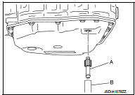
19. Install the charging pipe set (KV311039S0) (A) into the drain hole.
CAUTION:
Tighten the charging pipe by hand.
20. Install the ATF changer hose (B) to the charging pipe.
CAUTION:
Press the ATF changer hose all the way onto the charging
pipe until it stops.
21. Fill approximately 3 liter (2-5/8 lmp qt) of the CVT fluid.
22. Remove the ATF changer hose and charging pipe, then install the drain plug.
NOTE
:
Perform this work quickly because CVT fluid leaks.
23. Lift down the vehicle.
24. Start the engine.
25. While depressing the brake pedal, shift the selector lever to the entire position from “P” to “L”, and shift it to the “P” position.
NOTE
:
Hold the lever at each position for 5 seconds.
26. Check that the CONSULT-III “Data monitor” in “FLUID TEMP” is 35°C (95°F) to 45°C (113°F).
27. Lift up the vehicle.
28. Remove the drain plug and confirm that the CVT fluid is drained from the overflow tube.
CAUTION:
Perform this work with the vehicle idling.
NOTE:
If the CVT fluid is not drained, refer to “Adjustment” and refill with the CVT fluid.
29. When the flow of CVT fluid slows to a drip, tighten the drain plug to the specified torque. TM-493, "Exploded View".
CAUTION:
Never reuse drain plug gasket.
30. Lift down the vehicle.
31. Select “Data Monitor” in “TRANSMISSION” using CONSULT-III.
32. Select “CONFORM CVTF DETERIORTN”.
33. Select “Erase”.
34. Stop the engine.
Adjustment
CVT fluid : Refer to TM-512, "General Specification".
Fluid capacity : Refer to TM-512, "General Specification".
CAUTION:
• Use only Genuine NISSAN CVT Fluid NS-2. Using transmission fluid other than
Genuine NISSAN
CVT Fluid NS-2 will damage the CVT, which is not covered by the (NISSAN new
vehicle limited) warranty.
• During adjustment of the CVT fluid level, check CONSULT-III so that the oil temperature may be maintained from 35 to 45°C (95 to 113°F).
• Use caution when looking into the drain hole as there is a risk of dripping fluid entering the eye.
1. Check that the selector lever is in the “P” position, then completely engage the parking brake.
2. Start the engine.
3. Adjust the CVT fluid temperature to be approximately 40°C (104°F).
NOTE
:
The CVT fluid is largely affected by temperature. Therefore be sure to use
CONSULT-III and check the
“FLUID TEMP” under “TRANSMISSION” in “Data Monitor” while adjusting.
4. While depressing the brake pedal, shift the selector lever to the entire position from “P” to “L”, and shift it to the “P” position.
NOTE
:
Hold the lever at each position for 5 seconds.
5. Lift up the vehicle.
6. Check that there is no CVT fluid leakage.
7. Remove the drain plug. Refer to TM-493, "Exploded View".
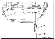
8. Install the charging pipe set (KV311039S0) (A) into the drain plug hole.
CAUTION:
Tighten the charging pipe by hand.
9. Install the ATF changer hose (B) to the charging pipe.
CAUTION:
Press the ATF changer hose all the way onto the charging
pipe until it stops.
10. Fill approximately 0.5 liter (1/2 lmp qt) of the CVT fluid.
11. Remove the ATF changer hose from the charging pipe, and check that the CVT fluid drains out from the charging pipe. If it does not drain out, perform charging again.
CAUTION:
Perform this work with the vehicle idling.
12. When the flow of CVT fluid slows to a drip, remove the charging pipe from the oil pan.
13. Tighten the drain plug to the specified torque. Refer to TM-493, "Exploded View".
CAUTION:
Never reuse drain plug gasket.
14. Lift down the vehicle.
15. Stop the engine.
 G sensor calibration
Description
TCM stores calibration data (inherent characteristic value) of G sensor to
provide accurate control. Therefore,
it is required to perform calibration of G sensor after the following wo ...
 Stall test
Work Procedure
INSPECTION
1. Check the engine oil level. Replenish if necessary. Refer to LU-25,
"Inspection".
2. Check for leak of the CVT fluid. Refer to TM-480, "Inspection" ...
Other materials:
B1131 side air bag module RH
DTC Logic
DTC DETECTION LOGIC
DTC CONFIRMATION PROCEDURE
1.CHECK SELF-DIAG RESULT
With CONSULT-III
1. Turn ignition switch ON.
2. Perform “Self Diagnostic Result” mode of “AIR BAG” using CONSULT-III.
Without CONSULT-III
1. Turn ignition switch ON.
2. Check the air bag warning lamp statu ...
A/C on signal
Component Function Check
1.CHECK A/C ON SIGNAL
With CONSULT-III
1. Turn ignition switch ON.
2. Operate blower motor.
3. Select “AIR CONDITIONER” of “BCM” using CONSULT-III.
4. Select “AIR COND SW” in “DATA MONITOR” mode.
5. Check A/C ON signal when the A/C switch is operated.
Is the inspec ...
Lubricant
Description
MAINTENANCE OF LUBRICANT LEVEL
The compressor lubricant is circulating in the system together with the
refrigerant. It is necessary to fill compressor
with lubricant when replacing A/C system parts or when a large amount of
refrigerant leakage is
detected. It is important to alwa ...
