Nissan Juke Service and Repair Manual : Cooling fan
Exploded View
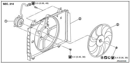
1. Fan motor
2. Fan shroud
3. Cooling fan
A. Apply on fan motor shaft
 : Apply genuine high strength
thread locking sealant or equivalent.
 : N·m (kg-m, in-lb)
Removal and Installation
REMOVAL
1. Drain engine coolant from radiator. Refer to CO-37, "Draining".
CAUTION:
• Perform this step engine is cold.
• Never spill engine coolant on drive belt.
2. Remove air duct (inlet) and resonator assembly. Refer to EM-161, "Removal and Installation".
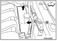
3. Remove reservoir tank as follows: a. Disconnect reservoir tank hose.
b. Release the tab (A) in the direction shown by the arrow (
 ).
).
c. Lift up and remove the reservoir tank with the tab released.
4. Remove radiator hose (upper). Refer to CO-42, "Exploded View".
5. Disconnect harness connector from fan motor, and move harness to aside.
6. Remove cooling fan assembly.
CAUTION:
Be careful not to damage or scratch on radiator core when removing.
INSTALLATION
Note the following, and install in the reverse order of removal.
CAUTION:
Only use genuine parts for fan shroud mounting bolt and observe the specified
torque (to prevent
radiator from being damaged).
NOTE:
Cooling fan is controlled by ECM. For details, Refer to EC-774, "Component Function Check".
Disassembly and Assembly
DISASSEMBLY
1. Remove cooling fan mounting nut, and then remove the cooling fan.
2. Remove fan motor.
ASSEMBLY
Note the following, and assemble in the reverse order of disassembly.
• Apply genuine high strength thread locking sealant on fan motor shaft.
Inspection
Cooling Fan
Inspect cooling fan for crack or unusual bend.
• If anything is found, replace cooling fan.
 Radiator
Exploded View
1. Reservoir tank hose
2. Mounting rubber (upper)
3. Radiator tank cap
4. Radiator
5. Mounting rubber (lower)
6. O-ring
7. Drain plug
8. Clamp
9. Radiator hose (lower)
...
 Water pump
Exploded View
1. Gasket
2. Water pump
3. Water pump pulley
: Always replace after every
disassembly.
: N·m (kg-m, in-lb)
: N·m (kg-m, ft-lb)
Removal and Installation
REMOVAL
1. Drain en ...
Other materials:
Checking engine oil level
1. Park the vehicle on a level surface and apply the parking brake.
2. Run the engine until it reaches operating temperature.
3. Turn off the engine. Wait more than 10 minutes for the oil to drain back into
the oil pan.
4. Remove the dipstick and wipe it clean.
Reinsert it all the way.
5. R ...
P1864 input speed signal
DTC Logic
DTC DETECTION LOGIC
DTC CONFIRMATION PROCEDURE
1.PRECONDITIONING
If “DTC CONFIRMATION PROCEDURE” has been previously conducted, always turn
ignition switch OFF and
wait at least 10 seconds before conducting the next test.
>> GO TO 2.
2.DTC REPRODUCTION PROCEDURE
With ...
Oil filter
Exploded View
1. O-ring
2. Oil filter bracket
3. Oil pressure switch
4. Oil filter
5. O-ring
6. Connecting bolt
A. To oil cooler
: N·m (kg-m, ft-lb)
: Always replace after every
disassembly.
Removal and Installation
REMOVAL
1. Using an oil filter wrench [SST:KV113C0010 (Mot.1329) ...
