Nissan Juke Service and Repair Manual : Cooler pipe and hose
Exploded View
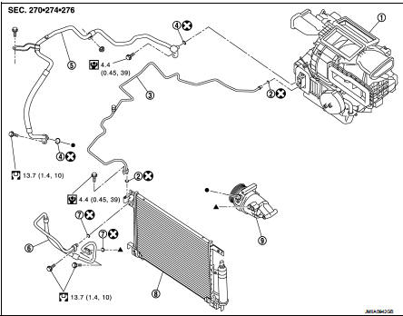
1. A/C unit assembly
2. O-ring
3. High-pressure pipe
4. O-ring
5. Low-pressure flexible hose
6. High-pressure flexible hose
7. O-ring
8. Condenser
9. Compressor
 : Do not reuse
 : N·m (kg-m, in-lb)
 : N·m (kg-m, ft-lb)
High-pressure flexible hose : Removal and Installation
CAUTION:
Perform lubricant return operation before each refrigeration system disassembly.
However, if a large
amount of refrigerant or lubricant is detected, never perform lubricant return
operation. Refer to HA-
78, "Perform Lubricant Return Operation".
REMOVAL
1. Use a refrigerant collecting equipment (for HFC-134a) to discharge the refrigerant. Refer to HA-76, "Recycle Refrigerant".
2. Remove front bumper fascia assembly. Refer to EXT-13, "Removal and Installation".
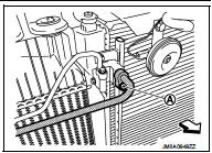
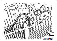
3. Remove mounting bolt (A), and then disconnect high-pressure flexible hose from condenser.
CAUTION:
Cap or wrap the joint of the A/C piping and condenser with
suitable material such as vinyl tape to avoid the entry of air.
 : Vehicle front
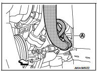
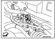
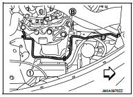
4. Remove mounting bolt (A), and then disconnect high-pressure flexible hose from compressor.
CAUTION:
Cap or wrap the joint of the A/C piping and compressor with
suitable material such as vinyl tape to avoid the entry of air.
 : Vehicle front
5. Remove high-pressure flexible hose from vehicle.
INSTALLATION
Note the following items, and then install in the reverse order of removal.
CAUTION:
• Replace O-rings with new ones. Then apply compressor oil to them when
installing.
• Check for leakages when recharging refrigerant. Refer to HA-74, "Leak Test".
Low-pressure flexible hose : Removal and Installation
CAUTION:
Perform lubricant return operation before each refrigeration system disassembly.
However, if a large
amount of refrigerant or lubricant is detected, never perform lubricant return
operation. Refer to HA-
78, "Perform Lubricant Return Operation".
REMOVAL
1. Use a refrigerant collecting equipment (for HFC-134a) to discharge the refrigerant. Refer to HA-76, "Recycle Refrigerant".
2. Remove front bumper fascia asembly. Refer to EXT-13, "Removal and Installation".
3. Remove cowl top extension. Refer to EXT-20, "Removal and Installation".
4. Remove mounting nut, and then move lower dash insulator aside.
 : Nut
: Nut
 : Vehicle front
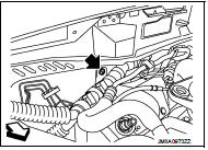
5. Remove mounting bolt (A), and then disconnect low-pressure flexible hose (1) and high-pressure pipe (2) from expansion valve. Refer to HA-116, "EXPANSION VALVE : Removal and Installation".
CAUTION:
Cap or wrap the joint of the A/C piping and expansion valve
with suitable material such as vinyl tape to avoid the entry
of air.
: Vehicle front
6. Remove mounting bolt (A) of low-pressure flexible hose front side (1) and mounting nut (B) of low-pressure flexible hose rear side (2).
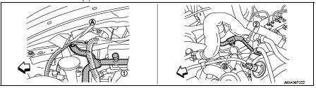
: Vehicle front
7. Remove ground wire mounting bolt (A), and then move ground wire (1) aside.
: Vehicle front
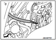
8. Remove mounting bolt (A), and then disconnect low-pressure flexible hose from compressor.
CAUTION:
Cap or wrap the joint of the A/C piping and compressor with
suitable material such as vinyl tape to avoid the entry of air.
: Vehicle front
9. Remove low-pressure flexible hose from vehicle.
INSTALLATION
Note the following items, and then install in the reverse order of removal.
CAUTION:
• Replace O-rings with new ones. Then apply compressor oil to them when
installing.
• Check for leakages when recharging refrigerant. Refer to HA-74, "Leak Test".
High-pressure pipe : Removal and Installation
CAUTION:
Perform lubricant return operation before each refrigeration system disassembly.
However, if a large
amount of refrigerant or lubricant is detected, never perform lubricant return
operation. Refer to HA-
78, "Perform Lubricant Return Operation".
REMOVAL
1. Use a refrigerant collecting equipment (for HFC-134a) to discharge the refrigerant. Refer to HA-76, "Recycle Refrigerant".
2. Remove low-pressure flexible hose. Refer to HA-91, "LOW-PRESSURE FLEXIBLE HOSE : Removal and Installation".
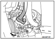
3. Remove mounting bolt (A), and then disconnect high-pressure pipe (1) from condenser.
CAUTION:
Cap or wrap the joint of the A/C piping and condenser with
suitable material such as vinyl tape to avoid the entry of air.
: Vehicle front
4. Remove high-pressure pipe (1) fixing clips (B), and then remove high-pressure pipe from vehicle.
: Vehicle front
INSTALLATION
Note the following items, and then install in the reverse order of removal.
CAUTION:
• Replace O-rings with new ones. Then apply compressor oil to them when
installing.
• Check for leakages when recharging refrigerant. Refer to HA-74, "Leak Test".
 Compressor
Exploded View
REMOVAL
1. High-pressure flexible hose
2. O-ring
3. Compressor
4. O-ring
5. Low-pressure flexible hose
A. To condenser
B. To evaporator
: N·m (kg-m, ft-lb)
DISASSEMBLY
...
 Condenser
Exploded View
1. Condenser
2. Condenser lower bracket RH
3. Condenser lower bracket LH
4. O-ring
5. Liquid tank braket
6. Liquid tank
7. Braket
8. O-ring
9. Refrigerant pressure senso ...
Other materials:
Precaution for Brake Control system
• Always perform a pre-driving check to drive the vehicle.
• Always check speed and safety while driving the vehicle.
• To operate CONSULT-III while driving, more than one person is required to be
in the vehicle to avoid interference
to driving and ensure safety.
• Slight vibrations are felt o ...
Camera image signal circuit
Description
• The NAVI control unit supplies power to the rear view camera when receiving
a reverse signal.
• The rear view camera transmits camera images to the NAVI control unit when
power is supplied from the
NAVI control unit.
Diagnosis Procedure
1.CHECK CONTINUITY CAMERA POWER SUPPLY C ...
ECU diagnosis information
ABS actuator and electric unit (control unit)
Reference Value
CONSULT-III DATA MONITOR STANDARD VALUE
*1: Confirm tire pressure is standard value.
*2: Refer to “valve operation” in BRC-105, "System Description" for valve
operation of each valve.
*3: Refer to BRC-105, "Sys ...
