Nissan Juke Service and Repair Manual : Control valve
Exploded View
COMPONENT PARTS LOCATION
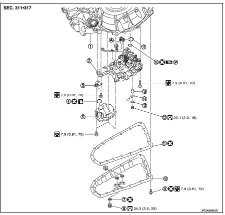
1. Transaxle assembly
2. Control valve
3. Bracket
4. O-ring
5. Oil strainer assembly
6. Magnet
7. Drain plug gasket
8. Drain plug
9. Oil pan mounting bolt
10. Oil pan
11. Oil pan gasket
12. Lock nut
13. Washer
14. Manual plate
15. Collar
16. Lip seal
17. Snap ring
A. CVT unit connector
 : Always replace after every
disassembly.
 : N·m (kg-m, ft-lb)
 : N·m (kg-m, in-lb)
 : NISSAN CVT Fluid NS-2
Removal and Installation
REMOVAL
1. Disconnect battery cable from negative terminal. Refer to PG-124, "Removal and Installation".
2. Remove drain plug from oil pan and then drain the CVT fluid.
3. Remove drain plug gasket.
4. Disconnect the CVT unit connector. Refer to TM-125, "Removal and Installation Procedure for CVT Unit Connector".
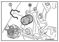
5. Remove the snap ring (1) from the CVT unit connector (A).
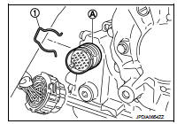
6. Press the CVT unit connector (A) into the transaxle case.
CAUTION:
Never damage the CVT unit connector.
NOTE:
Clean around the connector to prevent foreign materials from entering into the transaxle case.
7. Remove the oil pan mounting bolts, and then remove the oil pan and oil pan gasket.
8. Remove the magnets from the oil pan.
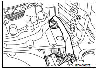
9. Remove the lock nut (1) and washer (2), and then remove the manual plate (3).
 : Vehicle front
10. Remove the collar (4) from the manual shaft (A).
CAUTION:
Never drop the collar.
11. Disconnect the connectors (A) and (B).
 : Clip
 : Vehicle front
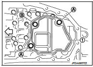
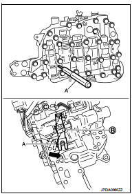
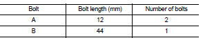
12. Remove the oil strainer assembly mounting bolts (A) and (B), and then remove the oil strainer assembly (1).
: Vehicle front
13. Remove O-ring from oil strainer assembly.
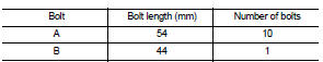
14. Remove the bracket (1).
: Bolt
: Vehicle front
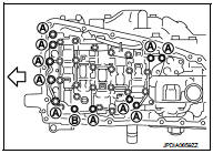
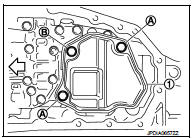
15. Remove the control valve mounting bolts (A) and (B), and then remove the control valve from the transaxle case.
: Vehicle front
CAUTION:
Never drop the control valve, ratio control valve and manual
shaft.
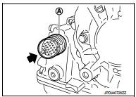
16. Remove CVT unit connector (A) from the transaxle case inside.
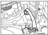
17. Remove the lip seal (1) from the transaxle case.
: Vehicle front
INSTALLATION
1. Install the lip seal (1) to the transaxle case.
: Vehicle front
2. Install the CVT unit connector (A) to the transaxle case.
CAUTION:
Connect the CVT unit connector with the stopper facing up,
and then press in until it clicks.
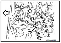
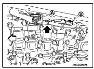
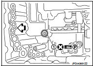
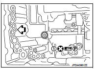
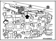
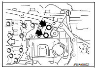
3. Press in the ratio control valve (B) in the (
) direction, and then
fix the linkage in the position shown in the figure with the linkage
fixing pin (A) from the back of control valve through the hole for
fixing.
4. Check that one end of linkage engages with the step motor end (C) and that the linkage is in the direction shown in the figure.
5. Install the control valve to the transaxle case.
CAUTION:
• Never drop the linkage fixing pin. If it is dropped, repeat
the installation procedure from step 3.
• Never pinch the harness into between the control valve and the transaxle case.
6. Fix the control valve using the control valve mounting bolts (A) and (B).
: Vehicle front
7. Pull the linkage fixing pin out.
8. Connect the connectors (A) and (B).
: Clip
: Vehicle front
CAUTION:
• Never pinch the harness into between the control valve
and the transaxle case.
• Securely insert the connector until it clicks and locks.
9. Install the bracket (1).
: Bolt
: Vehicle front
10. Install O-ring to oil strainer assembly.
CAUTION:
• Never reuse O-ring.
• Apply CVT fluid NS-2 to O-ring.
11. Install the oil strainer assembly (1) using the oil strainer assembly mounting bolts (A) and (B).
: Vehicle front
NOTE
:
Remove the bracket and adjust the position again if the bolt hole
positions are not aligned.
12. Install the collar to the manual shaft.
CAUTION:
Never drop the collar.
13. Install the manual plate (1) while aligning with the groove (A) of the manual valve.
CAUTION:
Assemble the manual plate while aligning its end with the
cutout (
) of the manual
valve.
: Vehicle front
14. Install the washer (2) and the lock-nut (3), and then tighten to the specified torque.
15. Install the snap ring (1) to the CVT unit connector (A).
16. Connect the CVT unit connector. Refer to TM-125, "Removal and Installation Procedure for CVT Unit Connector".
17. Install the magnet while aligning it with the convex side of oil pan.
CAUTION:
Completely eliminate the iron powder from the magnet
mounting area of oil pan and the magnet.
18. Install the oil pan to the transaxle case with the following procedure.
1. Install the oil pan gasket to the oil pan.
CAUTION:
• Completely wipe out any moisture, oil, and old gasket from the oil pan gasket
mounting surface
and bolt mounting hole of oil pan and transaxle case.
• Never reuse oil pan gasket.
2. Install the oil pan assembly to the transaxle case, and then temporarily tighten the oil pan mounting bolt.
CAUTION:
Never reuse oil pan mounting bolts.
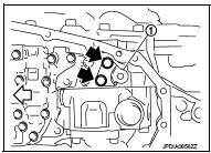
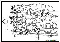
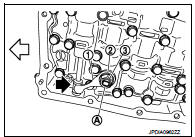
3. Tighten the oil pan mounting bolts in the order shown in the figure to the specified torque.
4. Tighten the oil pan mounting bolts again clockwise from (1) shown in the figure to the specified torque.

19. Install drain plug gasket to drain plug.
CAUTION:
Never reuse drain plug gasket.
20. Install drain plug to oil pan.
21. Fill CVT fluid from CVT fluid charging pipe to the specified level.
CVT fluid : Refer to TM-308, "General Specification".
Fluid capacity : Refer to TM-308, "General Specification".
CAUTION:
• Use only Genuine NISSAN CVT Fluid NS-2. Never mix with other fluid.
• Using CVT fluid other than Genuine NISSAN CVT Fluid NS-2 will deteriorate in driveability and CVT durability, and may damage the CVT, which is not covered by the warranty.
• When filling CVT fluid, take care not to scatter heat generating parts such as exhaust.
• Sufficiently shake the container of CVT fluid before using.
• Delete CVT fluid deterioration date with CONSULT-III after changing CVT fluid. Refer to TM-159, "CONSULT-III Function (TRANSMISSION)".
22. With the engine warmed up, drive the vehicle in an urban area.
NOTE
:
When ambient temperature is 20°C (68°F), it takes about 10 minutes for the CVT
fluid to warm up to 50
to80°C (122 to 176°F).
23. Check CVT fluid level and condition. Refer to TM-184, "Inspection".
24. Connect battery cable to negative terminal. Refer to PG-124, "Removal and Installation".
Inspection and Adjustment
INSPECTION AFTER REMOVAL
Check oil pan for foreign material.
• If a large amount of worn material is found, clutch plate may be worn.
• If iron powder is found, bearings, gears, or clutch plates may be worn.
• If aluminum powder is found, bushing may be worn, or chips or burrs of aluminum casting parts may enter.
Check points where wear is found in all cases.
INSPECTION AFTER REMOVAL
Check the CVT fluid level and leakage. Refer to TM-184, "Inspection".
INSPECTION AFTER INSTALLATION
Erase the TCM data.
• Erase the CVT fluid degradation data. Refer to TM-159, "CONSULT-III Function (TRANSMISSION)".
• When replacing the control valve, erase EEP ROM in TCM. Refer to TM-180, "Description".
 G sensor
Exploded View
1. G sensor
: Vehicle front
: N·m (kg-m, in-lb)
Removal and Installation
CAUTION:
• Never drop or strike G sensor, because it has little tolerance for impact.
• Never use a powe ...
 Primary speed sensor
Exploded View
1. Transaxle assembly
2. O-ring
3. Primary speed sensor
: Always replace after every
disassembly.
: N·m (kg-m, in-lb)
: Genuine NISSAN CVT Fluid NS-2
Removal and Installatio ...
Other materials:
Magnet clutch
Component Function Check
1.CHECK MAGNET CLUTCH OPERATION
Perform auto active test of IPDM E/R. Refer to PCS-12, "Diagnosis
Description" (with Intelligent Key) or PCS-
43, "Diagnosis Description" (without Intelligent Key).
Does it operate normally?
YES >> INSPECTION ...
Precaution
Precaution for Supplemental Restraint System (SRS) "AIR BAG" and "SEAT
BELT
PRE-TENSIONER"
The Supplemental Restraint System such as “AIR BAG” and “SEAT BELT PRE-TENSIONER”,
used along
with a front seat belt, helps to reduce the risk or severity of injury to the
driver a ...
Exploded View
1. Mounting rubber
2. Main muffler
3. Seal bearing
4. Spring
5. Mounting rubber
6. Seal bearing
7. Exhaust front tube
8. Heated oxygen sensor 2
9. Sub muffler
10. Gasket
: Always replace after every
disassembly.
: N·m (kg-m, ft-lb)
...
