Nissan Juke Service and Repair Manual : Control cable
Exploded View
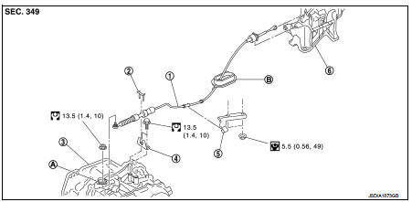
1. Control cable
2. Lock plate
3. Transaxle assembly
4. Bracket A
5. Bracket B
6. CVT shift selector assembly
A: Manual lever
B: Grommet
 : N·m (kg-m, ft-lb)
 : N·m (kg-m, in-lb)
Removal and Installation
INSTALLATION
CAUTION:
Always apply the parking brake before performing removal and installation.
1. Remove the battery. Refer to PG-124, "Removal and Installation".
2. Remove the control cable from the CVT shift selector assembly. Refer to TM-481, "Removal and Installation".
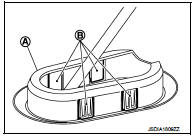
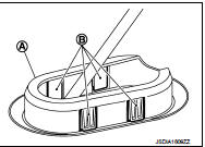
3. Disengage the pawls (B) of the grommet (A), and pull downwards to remove.
4. Remove the control cable installation nut from the manual lever.
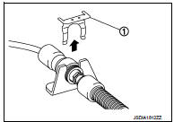
5. Remove the lock plate (1).
6. Remove sub muffler from the mounting rubber and lower the sub muffler downward. Refer to EX-12, "Exploded View".
7. Lift up the heat plate.
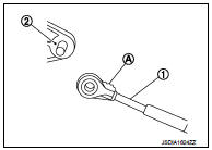
8. Remove the control cable (1) from the bracket (2).
 :Vehicle front
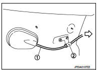
9. Remove the control cable from the vehicle.
10. Remove bracket.
INSTALLATION
Note the following, and install in the reverse order of removal.
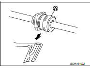
• From below the vehicle, press the grommet (A) into place until the pawls (B) make a click sound.
CAUTION:
• Place the grommet on the floor, then fasten it in place from
below the vehicle.
• Check that pulling down on the grommet does not disconnect it.
• Pay attention to the following when connecting the control cable to the CVT shift selector.
1. When connecting the control cable (1) to the CVT shift selector assembly (2), face the grooved surface of the rib (A) up and insert the control cable until it stops.
2. Install the socket (A) onto the CVT shift selector.
CAUTION:
• Place the socket onto the CVT shift lever, then fasten it in
place from above.
• Check that the pulling on the socket does not disconnect it.
Inspection
INSPECTION AFTER INSTALLATION
Check the CVT position. If a malfunction is found, adjust the CVT position. Refer to TM-383, "Inspection and Adjustment".
 CVT shift selector
Exploded View
1. Selector lever knob
2. Lock pin
3. Knob cover
4 Position indication panel
5. CVT shift selector assembly
6. CVT shift selector harness assembly
7. Detent switch*
8. Shi ...
 Key interlock cable
Exploded View
1. CVT shift selector assembly
2. Key interlock cable
A: Key cylinder
B: Clip
C: Clip
Removal and Installation
REMOVAL
CAUTION:
Always apply the parking brake before perfor ...
Other materials:
DTC/circuit diagnosis
Blower motor
Diagnosis Procedure
1.CHECK SYMPTOM
Check symptom (A or B).
Which symptom is detected?
A >> GO TO 2.
B >> GO TO 7.
2.CHECK FUSE
1. Turn ignition switch OFF.
2. Check 15A fuses (Nos. 14 and 16, located in fuse block (J/B)].
NOTE:
Refer to PG-22, "Fuse, ...
Windows
POWER WINDOWS
WARNING
• Make sure that all passengers have their hands, etc. inside the vehicle
while it is in motion and before closing the windows. Use the window lock switch
to prevent unexpected use of the power windows.
• Do not leave children unattended inside the vehicle. They could un ...
P0420 three way catalyst function
DTC Logic
DTC DETECTION LOGIC
The ECM monitors the switching frequency ratio of air fuel ratio (A/F)
sensor 1 and heated oxygen sensor 2.
A three way catalyst (manifold) with high oxygen storage capacity
will indicate a low switching frequency of heated oxygen sensor 2.
As oxygen storage c ...
