Nissan Juke Service and Repair Manual : Consult-III/GST checking system
Description
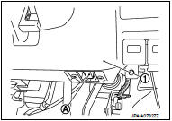
• When CONSULT-III/GST is connected with a data link connector (A) equipped on the vehicle side, it will communicate with the control unit equipped in the vehicle and then enable various kinds of diagnostic tests.
1 : Instrument lower panel RH
• Refer to CONSULT-III Software Operation Manual for more information.
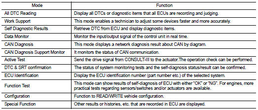
Consult-III Function and System Application*1
FUNCTION
SYSTEM APPLICATION*1
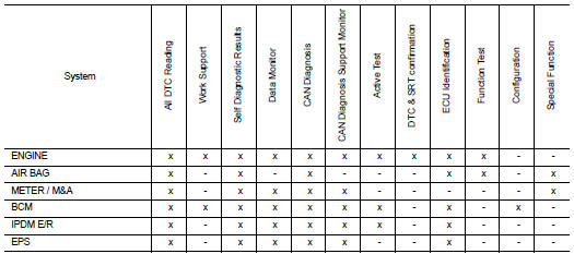
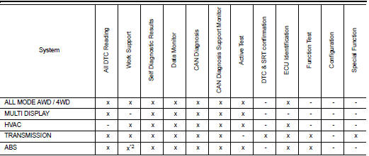
x: Applicable
*1 : If GST application is equipped, functions in accordance with SAE J1979 and
ISO 15031-5 can be used.
*2: With ESP models
Consult-III/GST Data Link Connector (DLC) Circuit
INSPECTION PROCEDURE
If the CONSULT-III/GST cannot diagnose the system properly, check the following items.
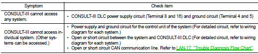
NOTE:
The DDL1 and DDL2 circuits from DLC pins 12, 13, 14 and 15 may be connected to more than one system. A short in a DDL circuit connected to a control unit in one system may affect CONSULT-III access to other systems.
If the GST cannot operate properly, check the circuit based on the information of SAE J1962 and ISO 15031- 3.
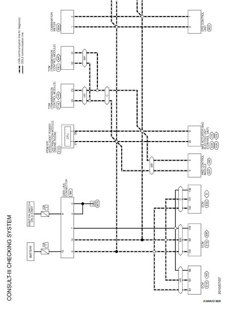
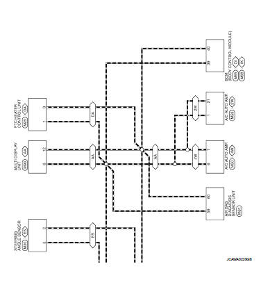
Wiring Diagram - Consult-III/GST checking system -
For connector terminal arrangements, harness layout, and alphabets in a
 (option abbreviation; if not
described in wiring diagram), refer to GI-12, "Connector Information/Explanation
of Option Abbreviation"
 Service information for electrical incident
Work Flow
WORK FLOW
Control Units and Electrical Parts
PRECAUTIONS
• Never reverse polarity of battery terminals.
• Install only parts specified for a vehicle.
• Before replacing the control ...
 Inspection and adjustment
ADDITIONAL SERVICE WHEN REMOVING BATTERY NEGATIVE TERMINAL
ADDITIONAL SERVICE WHEN REMOVING BATTERY NEGATIVE TERMINAL : Required
Procedure After Battery Disconnection
*: Not equipped. ...
Other materials:
Component parts
CVT control system : Component Parts Location
1. Multi display unit (MDU)*
Refer to DMS-3, "Component Parts
Location".
2. Combination meter 3. S mode indicator
(On the combination meter)
4. Shift position indicator
(On the combination meter)
5. Malfunction indicator lamp (MIL)
( ...
B27B0 A/C auto AMP.
DTC Logic
DTC DETECTION LOGIC
NOTE:
• If DTC is displayed along with DTC U1000, first perform the trouble diagnosis
for DTC U1000. Refer to HAC-
141, "DTC Logic".
• If DTC is displayed along with DTC U1010, first perform the trouble diagnosis
for DTC U1010. HAC-142,
"DTC Log ...
All-Wheel Drive (AWD) (if so equipped)
WARNING
• For AWD equipped vehicles, do not attempt to raise two wheels off
the ground and shift the transmission to any drive or reverse position with the
engine running. Doing so may result in drivetrain damage or unexpected vehicle movement
which could result in serious vehicle damag ...
