Nissan Juke Service and Repair Manual : Compression pressure
Inspection
1. Warm up engine thoroughly. Then, stop it.
2. Release fuel pressure. Refer to EC-551, "Work Procedure".
3. Remove ignition coil and spark plug from each cylinder. Refer to EM-53, "Exploded View".
4. Connect engine tachometer (not required in use of CONSULT-III).
5. Install compression gauge (B) with an adapter (A) (commercial service tool) onto spark plug hole.
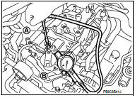
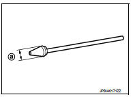
• Use the adapter whose picking up end inserted to spark plug hole is smaller than 20 mm (0.79 in) in diameter. Otherwise, it may be caught by cylinder head during removal.
a : 20 mm (0.79 in)
6. With accelerator pedal fully depressed, turn ignition switch to “START” for cranking. When the gauge pointer stabilizes, read the compression pressure and the engine rpm. Perform these steps to check each cylinder.
Compression pressure : Refer to EM-129, "General Specification".
CAUTION
:
Always use a fully charged battery to obtain the specified engine speed.
• If the engine speed is out of the specified range, check battery liquid for proper gravity. Check the engine speed again with normal battery gravity.
• If compression pressure is below minimum value, check valve clearances, and parts associated with combustion chamber (valve, valve seat, piston, piston ring, cylinder bore, cylinder head, and cylinder head gasket). After the checking, measure compression pressure again.
• If some cylinder has low compression pressure, pour small amount of engine oil into the spark plug hole of the cylinder to recheck it for compression.
- If the added engine oil improves the compression, piston rings may be worn out or damaged. Check piston rings and replace if necessary.
- If the compression pressure remains at low level despite the addition of engine oil, valves may be malfunctioning.
Check valves for damage. Replace valve or valve seat accordingly.
• If two adjacent cylinders have respectively low compression pressure and their compression remains low even after the addition of engine oil, cylinder head gaskets are leaking. In such a case, replace cylinder head gaskets.
7. After inspection is completed, install removed parts.
8. Start the engine, and check that the engine runs smoothly.
9. Perform trouble diagnosis. If DTC appears, erase it. Refer to EC-147, "Description".
 Camshaft valve clearance
Inspection and Adjustment
INSPECTION
Perform inspection as follows after removal, installation or replacement of
camshaft or valve-related parts, or if
there is unusual engine conditions regardin ...
 Symptom diagnosis
NOISE, VIBRATION AND HARSHNESS
(NVH) TROUBLESHOOTING
NVH troubleshooting Chart
1. Locate the area where noise occurs.
2. Confirm the type of noise.
3. Specify the operating condition of engine
...
Other materials:
ANTI-HIJACK function does not operate
Diagnosis Procedure
1.CHECK “DOOR LOCK–UNLOCK SET” SETTING IN “WORK SUPPORT”
1. Select “DOOR LOCK” of “BCM” using CONSULT-III.
2. Select “DOOR LOCK-UNLOCK SET” in “WORK SUPPORT” mode.
3. Check “DOOR LOCK-UNLOCK SET” in “WORK SUPPORT”
Refer to DLK-217, "DOOR LOCK : CONSULT-III Function (BCM ...
B1210 side collision detection
Description
The side air bag and curtain air bag are activated by the air bag diagnosis
sensor unit signal transmitted at the
time of side collision.
DTC Logic
DTC DETECTION LOGIC
DTC CONFIRMATION PROCEDURE
1.CHECK SELF-DIAG RESULT
With CONSULT-III
1. Turn ignition switch ON.
2. Perform ...
P0746 pressure control solenoid A
DTC Logic
DTC DETECTION LOGIC
NOTE:
DC stands for "DRIVING CYCLE" and indicates a series of driving cycle of
"Ignition switch OFF → ON → driving
→ OFF".
DTC CONFIRMATION PROCEDURE
CAUTION:
Be careful of the driving speed.
1.PREPARATION BEFORE WORK
...
