Nissan Juke Service and Repair Manual : Components
• THE LARGE ILLUSTRATIONS
are exploded views (see the following) and contain tightening torques, lubrication points, section number of the PARTS CATALOG (e.g. SEC. 440) and other information necessary to perform repairs.
The illustrations should be used in reference to service matters only. When ordering parts, refer to the appropriate PARTS CATALOG.
Components shown in an illustration may be identified by a circled number. When this style of illustration is used, the text description of the components will follow the illustration.
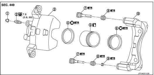
1. Cap
2. Bleeder valve
3. Cylinder body
4. Piston seal
5. Piston
6. Piston boot
7. Sliding pin
8. Sliding pin boot
9. Bushing
10. Torque member
 : Apply rubber grease.
 : Apply brake fluid.
 : N·m (kg-m, in-lb)
 : Always replace after every
disassembly
SYMBOLS
 Relation between Illustrations and Descriptions
The following sample explains the relationship between the part description
in an illustration, the part name in
the text and the service procedures.
...

Other materials:
P2119 electric throttle control function
DTC Logic
DTC DETECTION LOGIC
Diagnosis Procedure
1.CHECK INTERMITTENT INCIDENT
Refer to GI-42, "Intermittent Incident".
Is the inspection result normal?
YES >> GO TO 2.
NO >> Repair or replace.
2.REPLACE ELECTRIC THROTTLE CONTROL ACTUATOR
1. Replace electric t ...
System
System Diagram
System Description
REFRIGERANT CYCLE
Refrigerant Flow
The refrigerant from the compressor, flows the condenser with liquid tank, the
evaporator, and returns to the
compressor. The refrigerant evaporation in the evaporator is controlled by an
expansion valve.
Freeze Prote ...
Transmission range switch
Exploded View
1. Transmission range switch
2. Transaxle assem
Removal and Installation
REMOVAL
1. Remove battery. Refer to PG-124, "Removal and Installation".
2. Remove transmission range switch connector.
3. Remove control cable. Refer to TM-273, "Removal and Installation&q ...
