Nissan Juke Service and Repair Manual : Component parts
Component Parts Location
ENGINE ROOM COMPARTMENT
Top View
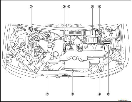
1. Priming pump
2. Turbocharger boost control solenoid
valve
3. Cooling fan motor
4. Refrigerant pressure sensor
5. IPDM E/R
6. ECM
7. Mass air flow sensor (with intake air
temperature sensor)
8. Electric throttle control actuator
9. Turbocharger boost sensor
Bottom View
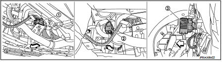
1. Thermoplunger
2. Glow relay
3. Thermoplunger control unit
ENGINE COMPARTMENT
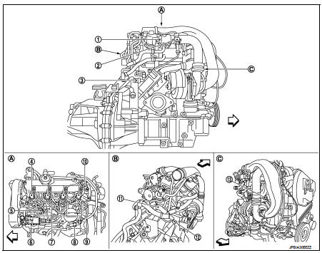
1. EGR volume control valve
2. Exhaust gas pressure sensor 1
3. Exhaust fuel injector
4. Fuel injector
5. Fuel temperature sensor
6. High pressure supply pump
7. Glow plug
8. Fuel rail pressure sensor
9. Fuel cut off valve
10. Camshaft position sensor
11. Engine coolant temperature sensor
12. Crankshaft position sensor
13. Exhaust gas temperature sensor 1
 :Engine front
EXHAUST COMPARTMENT
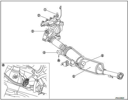
1. Exhaust gas pressure sensor 1 2. Exhaust gas temperature sensor 1 3. Exhaust fuel injector 4. Exhaust gas pressure sensor 2 5. DPF (Diesel particulate filter) 6. Exhaust gas temperature sensor 2
BODY COMPARTMENT
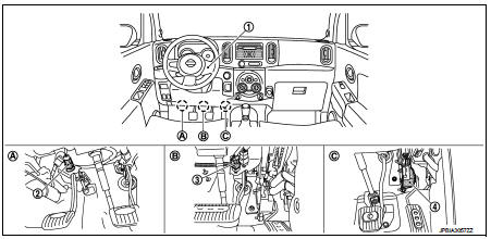
1. ASCD steering switch
2. Clutch pedal position switch
3. ASCD brake switch
4. Accelerator pedal position sensor
Component Description
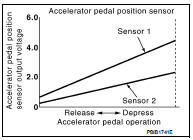
Accelerator Pedal Position Sensor
The accelerator pedal position sensor is installed on the upper end of the accelerator pedal assembly. The sensors detect the accelerator pedal position and sends a signal to the ECM. The ECM uses the signal to determine the amount of fuel to be injected.
ASCD Main Switch
When turning ON the ASCD MAIN switch, CRUISE is indicated on the information display and the operation mode turns to standby mode. When the ASCD MAIN switch turns OFF, the cruise control is released.
ASCD Steering Switch
ASCD steering switch has variant values of electrical resistance for each button. ECM reads voltage variation of switch, and determines which button is operated.
Barometric Pessure Sensor
The barometric pressure sensor is built into ECM. The sensor detects ambient barometric pressure and sends the voltage signal to the microcomputer.
Camshaft Position Sensor
The camshaft position (CMP) sensor senses the retraction with camshaft (left side) to identify a particular cylinder.
The camshaft position (CMP) sensor senses the piston position. When the crankshaft position (CKP) sensor system becomes inoperative, the camshaft position (CMP) sensor provides various controls of engine parts instead, utilizing timing of cylinder identification signals. The sensor consists of a permanent magnet and Hall IC.
Clutch Pedal Position Switch
Clutch switch signal is applied to the ECM through the clutch pedal position switch when the clutch pedal is depressed.
Cooling Fan
Cooling fan operates at each speed when the current flows in the cooling fan motor as follows.
Refer to EC-827, "COOLING FAN CONTROL : System Description" for cooling fan operation.
Crankshaft Position Sensor
The crankshaft position (CKP) sensor is located on the cylinder block rear housing facing the gear teeth (cogs) of the signal plate.The ECM receives the voltage signal and detects the function of the engine revolution.
DPF (Diesel Particulate Filter)
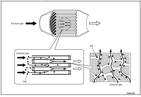
Diesel particulate filter is placed after oxidation catalyst and traps PM (Particulate Matter) in exhaust gas. Diesel particulate filter is a silicon carbide (SiC) gas permeable monolith in which ducts are alternately blocked.
This structure facilitates to trap particulate matter.
When the amount of particulate matter in the diesel particulate filter reaches the specified level, the particulate matter needs to be reduced through burning to maintain the diesel particulate filter function. This reducing of particulate matter is called Regeneration and should be performed periodically. Diesel particulate filter can be effective for a long time through the cycle of trapping particulate matter and regeneration.
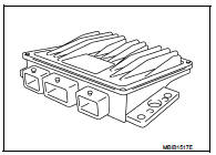
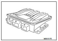
ECM
The ECM consists of a microcomputer and connectors for signal input and output and for power supply. The ECM controls the engine.
EGR Cooler Bypass Control Solenoid Valve
EGR cooler bypass control solenoid valve controls vacuum signal to the EGR cooler bypass valve control actuator. ERG amount is controlled by changing the EGR cooler bypass valve opening using the rod. EGR cooler bypass valve control solenoid valve is operated by ON/OFF signals (pulse signals) sent from ECM.
Thelonger is the ON pulse duration, the larger becomes the bypass gas volume.
Electric Throttle Control Actuator
By default the valve is open when in the rest position and is actuated only when the engine is stopped; this has a damping effect and helps to stop the engine.
Engine Coolant Temperature Sensor
The engine coolant temperature sensor is used to detect the engine coolant temperature. The sensor modifies a voltage signal from the ECM. The modified signal returns to the ECM as the engine coolant temperature input. The sensor uses a thermistor which is sensitive to the change in temperature. The electrical resistance of the thermistor decreases as temperature increases.
Exhaust Fuel Injector
The exhaust fuel injector is installed before oxidation catalyst.
During diesel particulate filter regeneration, the ECM controls the exhaust fuel injector to inject the fuel and rises the exhaust gas temperature.
Exhaust Gas Pressure Sensor 1
Exhaust gas pressure sensor 1 is conected to exhaust manifold with exhasut pressure tube. Exhaust gas pressure sensor 1 measures the exhaust gas pressure and convers the pressure into a voltage signal.
Exhaust Gas Pressure Sensor 2
Exhaust gas pressure sensor 2 is connected to diesel particulate filter with exhaust pressure tube. Exhaust gas pressure sensor 2 measures the exhaust back pressure before the filter. It converts into a voltage signal.
ECM receives the signal and estimates the amount of particulate matter in diesel particulate filter.
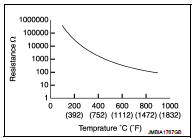
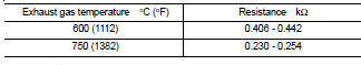
Exhaust Gas Temperature Sensor 1
The exhaust gas temperature sensor 1 is used to detect the exhaust gas temperature before turbocharger.
The sensor modifies a voltage signal from the ECM. The modified signal returns to the ECM as the exhaust gas temperature input. The sensor uses a thermistor which is sensitive to the change in temperature. The electrical resistance of the thermistor decreases as temperature increases.
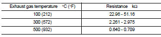
<Reference data>

*: This data is reference value and is measured between ECM terminal 64 (Exhaust gas temperature sensor 1) and ground.
CAUTION:
Do not use ECM ground terminals when measuring input/output voltage. Doing so
may result in damage
to the ECM's transistor. Use a ground other than ECM terminals, such as the
ground.
Exhaust Gas Temperature Sensor 2
The exhaust gas temperature sensor 2 is used to detect the exhaust gas temperature after oxidation catalyst.
The sensor modifies a voltage signal from the ECM. The modified signal returns to the ECM as the exhaust gas temperature input. The sensor uses a thermistor which is sensitive to the change in temperature. The electrical resistance of the thermistor decreases as temperature increases.
<Reference data>
Fuel Cut OFF Valve
The fuel cut off valve is in front of the exhaust fuel injector line. This valve is used to cut off the exhaust fuel injection line for the purpose of preventing fuel leakage when the injector is not being used or when a malfunction is detected in the injector
Fuel Rail Pressure Sensor
The fuel rail pressure (FRP) sensor is placed to the fuel rail. It measures the fuel pressure in the fuel rail. The sensor sends voltage signal to the ECM. As the pressure increases, the voltage rises. The ECM controls the fuel pressure in the fuel rail. The ECM uses the signal from fuel rail pressure sensor as a feedback signal.
Fuel Temperature Sensor
Fuel temperature sensor is built in the fuel pump. The sensor detects the fuel temperature in the fuel pump and calibrates the fuel injection amount change by fuel temperature.
Glow Relay
When ignition switch is turned ON while cooling temperature is lower than the specified value, ECM actuates glow plug through glow relay. Because of this, combustion chamber is warmed and stabilized combustion at starting can be obtained under low cooling temperature. The preheating time is determined according to cooling temperature, inlet air temperature and battery voltage.
Intake Air Temperature Sensor
The intake air temperature sensor is built into mass air flow sensor. The sensor detects intake air temperature and transmits a signal to the ECM.
The temperature sensing unit uses a thermistor which is sensitive to the change in temperature. Electrical resistance of the thermistor decreases in response to the temperature rise.
Malfunction Indicator
The OBD malfunction indicator [MI (Yellow)] is used to alert the driver to the existence of engine control system malfunctions involving excessive pollution or if the EOBD system is deactivated.
The ECM makes a request for lighting of the MI (Yellow) only where there is a malfunction present at the end of three consecutive cycles.
In the event of an engine malfunction, the ECM may request the display of an engine warning light [MI (Red)].
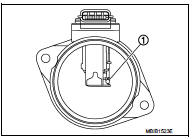
Mass Air Flow sensor
The mass air flow sensor is placed in the stream of intake air.
• Intake air temperature sensor (1)
Refrigerant Pressure Sensor
The refrigerant pressure sensor is installed at the condenser of the air conditioner system. The sensor uses an electrostatic volume pressure transducer to convert refrigerant pressure to voltage. The voltage signal is sent to ECM, and ECM controls cooling fan system.
Speed Limiter Main Switch
When turning ON the speed limiter MAIN switch, LIMIT is indicated on the information display and the operation mode turns to standby mode. When the speed limiter MAIN switch is turns OFF, the speed limiter control is released.
Thermoplunger Control Unit
Thermoplunger function to increase exhaust gas temperature as requirement for regeneration process.
It′s basically four glow plugs, it demands high power to alternator and engine compensate this strong demand increasing engine load, when engine load is increased then exhaust gas temperature is higher. These electrical glow plugs are cooled by flow water through pipe of device plungers.
Turbocharger Boost Sensor
The turbocharger boost sensor detects pressure in the exit side of the charge air cooler. The sensor output voltage to the ECM increases as pressure increases.

 System
ENGINE CONTROL SYSTEM : System Diagram
1. Priming pump
2. Fuel filter
3. High pressure supply pump
4. High pressure supply pump (internal
transfer pump)
5. High pressure supply pump (volumet ...
Other materials:
Operating range for engine start function
The Intelligent Key can only be used for starting the engine when the Intelligent
Key is within the specified operating range1 .
When the Intelligent Key battery is almost discharged or strong radio waves are
present near the operating location, the Intelligent Key system’s operating range
...
Hood
Exploded View
1. Hood assembly
2. Hood bumper rubber
3. Radiator core seal
4. Hood bumper rubber
5. Clamp
6. Hood hinge
7. Grommet
8. Hood support rod
: Clip
: Pawl
: Body grease
Hood assembly
HOOD ASSEMBLY : Removal and Installation
CAUTION:
• Operate with two workers, because ...
Engine oil
Inspection
ENGINE OIL LEVEL
NOTE:
Before starting engine, put vehicle horizontally and check the engine oil level.
If engine is already started, stop
it and allow 10 minutes before checking.
1. Pull out oil level gauge and wipe it clean.
2. Insert oil level gauge and check that the engine ...
