Nissan Juke Service and Repair Manual : Component parts
Automatic air conditioning system : Component Parts Location
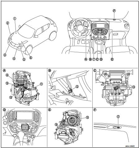
1. BCM
• With Intelligent Key: Refer to BCS-
6, "BODY CONTROL SYSTEM :
Component Parts Location".
• Without Intelligent Key: Refer to BCS-96, "BODY CONTROL SYSTEM : Component Parts Location".
2. Magnet clutch
3. Refrigerant pressure sensor
4. Ambient sensor
5. ECM
• HR16DE: Refer to EC-455, "ENGINE
CONTROL SYSTEM :
Component Parts Location".
• MR16DDT: Refer to EC-25, "ENGINE CONTROL SYSTEM : Component Parts Location".
• K9K: Refer to EC-813, "Component Parts Location".
6. IPDM E/R
• With Intelligent Key: Refer to PCS-
5, "Component Parts Location".
• Without Intelligent Key: Refer to PCS-37, "Component Parts Location".
7. Multi display unit
8. Intake door motor
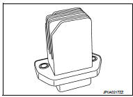
9. Fan control amp.
10. Air mix door motor
11. Intake sensor
12. In-vehicle sensor
13. Aspirator
14. A/C auto amp.
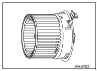
15. Blower motor
16. Mode door motor
17. Sunload sensor
A. Left side of A/C unit assembly B. Instrument lower panel LH is removed C. Back side of A/C unit assembly D. Multi display unit is removed E. Right side of A/C unit assembly C. Right side of switch panel
Automatic air conditioning system : Component Description
PTC heater control system : Component Parts Location
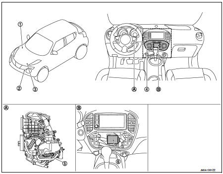
1. BCM
• With Intelligent Key: Refer to BCS-
6, "BODY CONTROL SYSTEM :
Component Parts Location".
• Without Intelligent Key: Refer to BCS-96, "BODY CONTROL SYSTEM : Component Parts Location".
2. Ambient sensor
3. ECM
Refer to EC-813.
4. Multi display unit
5. PTC heater
6. A/C auto amp.
A. Left side of A/C unit assembly B. Multi display unit is removed
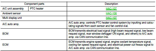
PTC heater control system : Component Description
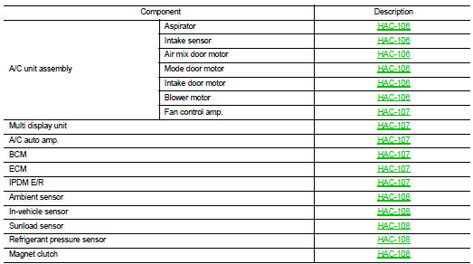
A/C unit assembly : Aspirator
The aspirator generates the vacuum by the air blown from the A/C unit assembly and draws the air of the passenger room to the invehicle sensor area via the aspirator duct.
A/C unit assembly : Intake Sensor
Intake sensor measures temperature of evaporator fin temperature. The sensor uses a thermistor which is sensitive to the change in temperature. The electrical resistance of the thermistor decreases as temperature increases
A/C unit assembly : Air Mix Door Motor
• Air mix door motor consists of motor that drives door, PBR (Potentio Balance Register) that detects door position and LCU (Local Control Unit) that perform multiplex communication control (LIN) with A/C auto amp.
Refer to HAC-114, "AUTOMATIC AIR CONDITIONING SYSTEM : Door Control".
• Rotation of motor is transmitted to air mix door (upper air mix door, lower air mix door, max. cool door) by link, rod, and lever. Air flow temperature is switched.
A/C unit assembly : Mode Door Motor
• Mode door motor consists of motor that drives door, PBR (Potentio Balance Register) that detects door position and LCU (Local Control Unit) that perform multiplex communication control (LIN) with A/C auto amp.
Refer to HAC-114, "AUTOMATIC AIR CONDITIONING SYSTEM : Door Control".
• Rotation of motor is transmitted to mode door (center ventilator door, side ventilator door, foot door, and defroster door) by link, rod, and lever. Air outlet is switched.
A/C unit assemblyY : Intake Door Motor
• Intake door motor consists of motor that drives door, PBR (Potentio Balance Register) that detects door position and LCU (Local Control Unit) that perform multiplex communication control (LIN) with A/C auto amp.
Refer to HAC-114, "AUTOMATIC AIR CONDITIONING SYSTEM : Door Control".
• Rotation of motor is transmitted to intake door by link and lever. Air inlet is switched.
A/C unit assembly : Blower Motor
• The blower motor utilizes a brush-less motor with a rotating magnet.
• Quietness is improved over previous motors where the brush was the point of contact and the coil rotated.
A/C unit assembly : Fan Control Amp
• Fan control amp., that uses MOS field effect transistor, is adopted for blower motor speed control.
NOTE
:
MOS field effect transistor is a transistor for which the gate portion
is composed of a metal electrode on an oxide layer of semiconductor.
Field effect transistor is controlled by voltage, while ordinary transistor is controlled by current. Electrode of field effect transistor is called source, drain, or gate, while electrode of ordinary transistor is called emitter, collector, or base.
• Fan control amp. continuously controls voltage to blower motor, according to gate voltage from A/C auto amp.
• This power transistor does not require a HI relay even when the maximum voltage is applied to blower motor at HI status, because voltage drop is nominal.
A/C unit assembly : PTC Heater
Heat element is heated and air flow temperature is increased by power supply from PTC relay.
Multi Display Unit
• Multi display unit integrates display and operation switches.
• Operation of each switch (A/C operation signal) and setting status (A/C ECO setting signal and ECO mode signal) are transmitted to A/C auto amp. via CAN communication.
• Operation status of air conditioning system is indicated in the display according to A/C display signal that is received from A/C auto amp.
A/C Auto Amp.
A/C auto amp. controls automatic air conditioning system by inputting and calculating signals from each sensor and each switch. A/C auto amp. has self-diagnosis function. Diagnosis of automatic air conditioning system can be performed quickly.
BCM
BCM transmits A/C ON signal and blower fan ON signal from A/C auto amp. to ECM via CAN communication line.
ECM
• ECM, when receiving A/C ON signal and blower fan ON signal from BCM, transmits A/C compressor request signal to IPDM E/R via CAN communication according to status of the engine and refrigerant pressure.
• ECM transmits engine coolant temperature signal to A/C auto amp. via CAN communication line.
IPDM E/R
A/C relay is integrated in IPDM E/R. IPDM E/R operates A/C relay when A/C compressor request signal is received from ECM via CAN communication line.
Ambient Sensor
Ambient sensor measures ambient air temperature. The sensor uses a thermistor which is sensitive to the change in temperature. The electrical resistance of the thermistor decreases as temperature increases.
In-vehicle Sensor
In-vehicle sensor measures temperature of intake air that flows through aspirator to passenger room. The sensor uses a thermistor which is sensitive to the change in temperature. The electrical resistance of the thermistor decreases as temperature increases.
Sunload Sensor
Sunload sensor measures sunload amount. This sensor converts sunload amount to voltage signal by photodiode and transmits to A/C auto amp.
Refrigerant Pressure Sensor
DESCRIPTION
• The refrigerant pressure sensor converts high-pressure side refrigerant pressure into voltage and outputs it to ECM.
• ECM operates cooling system protection and idle speed control according to voltage value that is input.
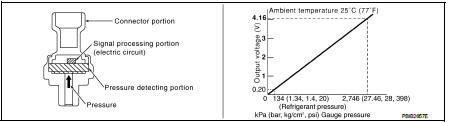
STRUCTURE AND OPERATION
• The refrigerant pressure sensor is a capacitance type sensor. It consists of a pressure detection ares and a signal processing area.
• The pressure detection area, which is a variable capacity condenser, changes internal static capacitance according to pressure force.
• The signal processing area detects the static capacitance of the pressure detection area, converts the static capacitance into a voltage value, and transmits the voltage value to ECM.
Magnet Clutch
Compressor is driven by the magnet clutch which is magnetized by electric power supply.

 System
Automatic air conditioning system : System Diagram
Automatic air conditioning system : System Description
DESCRIPTION
• Automatic air conditioning system is controlled by each function of A/C
a ...
Other materials:
B1068, B1073 passenger air bag module
DTC Logic
DTC DETECTION LOGIC
DTC CONFIRMATION PROCEDURE
1.CHECK SELF-DIAG RESULT
With CONSULT-III
1. Turn ignition switch ON.
2. Perform “Self Diagnostic Result” mode of “AIR BAG” using CONSULT-III.
Without CONSULT-III
1. Turn ignition switch ON.
2. Check the air bag warning lamp statu ...
Precaution for Liquid Gasket
REMOVAL OF LIQUID GASKET
• After removing the mounting bolts and nuts, separate the mating
surface using a seal cutter and remove the liquid gasket.
CAUTION:
Be careful not to damage the mating surfaces.
• In areas where the cutter is difficult to use, use a plastic hammer to
lightly tap the ...
Rear shock absorber
Exploded View
1. Suspension arm
2. Shock absorber
3. Bound bumper
4. Bound bumper cover
5. Washer
6. Bushing
7. Distance tube
8. Piston rod lock nut
9. Cap
: Vehicle front
: Always replace after every
disassembly.
: N·m (kg-m, ft-lb)
Removal and Installation
REMOVAL
1. Remove ...
