Nissan Juke Service and Repair Manual : Component parts
Component Parts Location
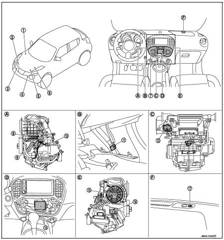
1. BCM
• With Intelligent Key: Refer to BCS-
6, "BODY CONTROL SYSTEM :
Component Parts Location".
• Without Intelligent Key: Refer to BCS-96, "BODY CONTROL SYSTEM : Component Parts Location".
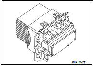
2. Magnet clutch 3. Refrigerant pressure sensor 4. Ambient sensor 5. ECM Refer to EC-25, "ENGINE CONTROL SYSTEM : Component Parts Location".
6. IPDM E/R
• With Intelligent Key: Refer to PCS-
5, "Component Parts Location".
• Without Intelligent Key: Refer to PCS-37, "Component Parts Location".
7. Multi display unit
8. Intake door motor
9. Air mix door motor
10. Intake sensor
11. In-vehicle sensor
12. Power transistor
13. Aspirator
14. A/C auto amp.
15. Blower motor
16. Mode door motor
17. Sunload sensor
A. Left side of A/C unit assembly B. Instrument lower panel LH is removed C. Back side of A/C unit assembly D. Multi display unit is removed E. Right side of A/C unit assembly F. Right side of switch panel
Component Description
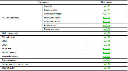
A/C unit assembly : Aspirator
The aspirator generates the vacuum by the air blown from the A/C unit assembly and draws the air of the passenger room to the invehicle sensor area via the aspirator duct.
A/C unit assembly : Intake Sensor
Intake sensor measures temperature of evaporator fin temperature. The sensor uses a thermistor which is sensitive to the change in temperature. The electrical resistance of the thermistor decreases as temperature increases.
A/C unit assembly: Air Mix Door Motor
• The step motor system is adopted for air mix door motor.
• When a drive signal is input from A/C auto amp. to door motor, a step motor built into the door the door motor rotates according to the drive signal, and then stops at the position of target door. Refer to HAC-21, "Door Control".
• Rotation of motor is transmitted to air mix door (upper air mix door and lower air mix door) by lod and lever.
Air flow temperature is switched.
A/C unit assembly: Mode Door Motor
• The step motor system is adopted for mode door motor.
• When a drive signal is input from A/C auto amp. to door motor, a step motor built into the door the door motor rotates according to the drive signal, and then stops at the position of target door. Refer to HAC-21, "Door Control".
• Rotation of motor is transmitted to mode door (center ventilator and defroster door, sub defroster door, side ventilator door, and foot door) by link, lod, and lever. Air outlet is switched.
A/C UNIT ASSEMBLY : Intake Door Motor
• Intake door motor consists of motor that drives door and PBR (Potentio Balance Register) that detects door position.
• Motor operates intake door according to control signal from A/C auto amp. Refer to HAC-21, "Door Control".
• Rotation of motor is transmitted to intake door by lever. Air inlet is switched.
• PBR (Potentio Balance Register) transmits PBR feedback signal to A/C auto amp. according to motor position.
• According to PBR feedback signal, A/C auto amp. monitors that motor is in an appropriate door position
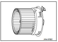
A/C unit assembly : Blower Motor
• The blower motor utilizes a brush-less motor with a rotating magnet.
• Quietness is improved over previous motors where the brush was the point of contact and the coil rotated.
A/C unit assembly : Power Transistor
• Power transistor, that uses MOS field effect transistor, is adopted for blower motor speed control.
NOTE
:
MOS field effect transistor is a transistor for which the gate portion
is composed of a metal electrode on an oxide layer of semiconductor.
Field effect transistor is controlled by voltage, while ordinary transistor is controlled by current. Electrode of field effect transistor is called source, drain, or gate, while electrode of ordinary transistor is called emitter, collector, or base.
• Power transistor continuously controls voltage to blower motor, according to gate voltage from A/C auto amp.
• This power transistor does not require a HI relay even when the maximum voltage is applied to blower motor at HI status, because voltage drop is nominal.
Multi Display Unit
• Multi display unit integrates display and operation switches.
• Operation of each switch (A/C operation signal) and setting status (A/C ECO setting signal and ECO mode signal) are transmitted to A/C auto amp. via CAN communication.
• Operation status of air conditioning system is indicated in the display according to A/C display signal that is received from A/C auto amp.
A/C Auto Amp.
A/C auto amp. controls automatic air conditioning system by inputting and calculating signals from each sensor and each switch. A/C auto amp. has self-diagnosis function. Diagnosis of automatic air conditioning system can be performed quickly.
BCM
BCM transmits A/C ON signal and blower fan ON signal from A/C auto amp. to ECM via CAN communication line.
ECM
• ECM, when receiving A/C ON signal and blower fan ON signal from BCM, transmits A/C compressor request signal to IPDM E/R via CAN communication according to status of the engine and refrigerant pressure.
• ECM transmits engine coolant temperature signal to A/C auto amp. via CAN communication line.
IPDM E/R
A/C relay is integrated in IPDM E/R. IPDM E/R operates A/C relay when A/C compressor request signal is received from ECM via CAN communication line.
Ambient Sensor
Ambient sensor measures ambient air temperature. The sensor uses a thermistor which is sensitive to the change in temperature. The electrical resistance of the thermistor decreases as temperature increases.
In-vehicle Sensor
In-vehicle sensor measures temperature of intake air that flows through aspirator to passenger room. The sensor uses a thermistor which is sensitive to the change in temperature. The electrical resistance of the thermistor decreases as temperature increases.
Sunload Sensor
Sunload sensor measures sunload amount. This sensor converts sunload amount to voltage signal by photodiode and transmits to A/C auto amp.
Refrigerant Pressure Sensor
DESCRIPTION
• The refrigerant pressure sensor converts high-pressure side refrigerant pressure into voltage and outputs it to ECM.
• ECM operates cooling system protection and idle speed control according to voltage value that is input.
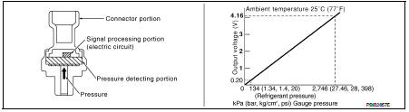
STRUCTURE AND OPERATION
• The refrigerant pressure sensor is a capacitance type sensor. It consists of a pressure detection ares and a signal processing area.
• The pressure detection area, which is a variable capacity condenser, changes internal static capacitance according to pressure force.
• The signal processing area detects the static capacitance of the pressure detection area, converts the static capacitance into a voltage value, and transmits the voltage value to ECM.
Magnet Clutch
Compressor is driven by the magnet clutch which is magnetized by electric power supply.

 System
System Diagram
System Description
DESCRIPTION
• Automatic air conditioning system is controlled by each function of A/C
auto amp., BCM, ECM and IPDM E/
R.
• Each operation of air conditioning ...
Other materials:
Output speed sensor
Exploded View
1. Transaxle assembly
2. Output speed sensor
3. O-ring
: Vehicle front
: Always replace after every
disassembly.
: N·m (kg-m, in-lb)
: Genuine NISSAN CVT Fluid NS-2
Removal and Installation
REMOVAL
1. Disconnect battery cable from negative terminal. Refer to PG-124, &qu ...
Wheel alignment
Inspection
DESCRIPTION
CAUTION:
• The adjustment mechanisms of camber, caster, and kingpin inclination angles
are not included.
• If camber, caster, or kingpin inclination angle is outside the standard, check
front suspension parts
for wear and damage. Replace suspect parts if a malfunction ...
High pressure supply pump
Exploded View
1. High pressure supply pump protector
2. High pressure supply pump
: N·m (kg-m, ft-lb)
Removal and Installation
REMOVAL
CAUTION:
• Be sure to read “Precautions for Diesel Equipment”. Refer to EM-263,
"Precaution for Diesel Equipment".
• Wait until the fuel tempe ...
