Nissan Juke Service and Repair Manual : Component parts
Component Parts Location
LHD
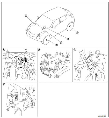
1. ABS actuator and electric unit (control
unit)
2. Front wheel sensor
3. Stop lamp switch
4. Rear wheel sensor
A. Inside engine room
B. Steering knuckle
C. Brake pedal
D. ABS warning lamp, brake warning
lamp (in combination meter)
E. Rear wheel hub and bearing assembly
RHD
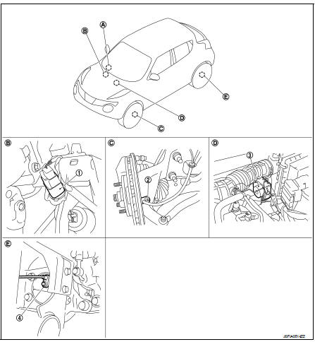
1. Stop lamp switch
2. Front wheel sensor
3. ABS actuator and electric unit (control
unit)
4. Rear wheel sensor
A. ABS warning lamp, brake warning
lamp (in combination meter)
B. Brake pedal
C. Steering knuckle
D. Inside engine room
E. Rear wheel hub and bearing assembly
Component Description

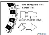
Wheel Sensor and Sensor Rotor
NOTE
:
• Wheel sensor of front wheel is installed on steering knuckle.
• Sensor rotor of front wheel is integrated in wheel hub and bearing assembly.
• Wheel sensor of rear wheel is installed on wheel hub and bearing assembly.
• Sensor rotor of rear wheel is integrated in wheel hub and bearing assembly.
• Never measure resistance and voltage value using a tester because sensor is active sensor.
• Downsize and weight reduction is aimed. IC for detection portion and magnet for sensor rotor are adopted.
• Power supply is supplied to detection portion so that magnetic field line is read. Magnetic field that is detected is converted to current signal.
• When sensor rotor rotates, magnetic field changes. Magnetic field change is converted to current signals (rectangular wave) and is transmitted to ABS actuator and electric unit (control unit). Change of magnetic field is proportional to wheel speed.
ABS Actuator and Electric Unit (Control Unit)
Electric unit (control unit) is integrated with actuator and comprehensively controls ABS function and EBD function.
ELECTRIC UNIT (CONTROL UNIT)
• Brake fluid pressure are controlled according to signals from each sensor.
• If malfunction is detected, the system enters fail-safe mode.
ACTUATOR
The following components are integrated with ABS actuator.
Pump
Returns the brake fluid reserved in reservoir to master cylinder by reducing
pressure.
Motor
Activates the pump according to signals from ABS actuator and electric unit
(control unit).
Motor Relay
Operates the motor ON/OFF according to signals from ABS actuator and electric
unit (control unit).
Actuator Relay (Main Relay) Operates each valve ON/OFF according to signals from ABS actuator and electric unit (control unit).
ABS IN Valve
Switches the fluid pressure line to increase or hold according to signals from
control unit.
NOTE
:
Valve is a solenoid valve.
ABS OUT Valve
Switches the fluid pressure line to increase, hold or decrease according to
signals from control unit.
NOTE
:
Valve is a solenoid valve.
Inlet Valve
Brake fluid sucked from the reservoir by the pump does not backflow.
NOTE
:
Valve is a check valve.
Outlet Valve
Brake fluid discharged from the pump does not backflow.
NOTE
:
Valve is a check valve.
Return Check Valve
Returns the brake fluid from brake caliper to master cylinder by bypassing
orifice of each valve when brake is
released.
Reservoir
Temporarily reserves the brake fluid drained from brake caliper, so that
pressure efficiently decreases when
decreasing pressure of brake caliper.
Stop Lamp Switch
Detects the operation status of brake pedal and transmits converted electric signal to ABS actuator and electric unit (control unit).

 System
System Description
• The system switches fluid pressure of each brake caliper to increase, to
hold or to decrease according to
signals from control unit in ABS actuator and electric unit (control ...
Other materials:
P1642 thermoplunger control unit
DTC Logic
DTC DETECTION LOGIC
Diagnosis Procedure
1.CHECK THERMOPLUNGER CONTROL UNIT POWER SUPPLY CIRCUIT
1. Turn ignition switch OFF.
2. Disconnect thermoplunger control unit harness connector.
3. Check the voltage between thermoplunger control unit harness connector and
ground.
Is the ...
Magnet clutch
Component Function Check
1.CHECK MAGNET CLUTCH OPERATION
Perform auto active test of IPDM E/R. Refer to PCS-12, "Diagnosis
Description" (with Intelligent Key) or PCS-
43, "Diagnosis Description" (without Intelligent Key).
Does it operate normally?
YES >> INSPECTION ...
Service Notice or Precautions for Clut
WARNING:
After cleaning clutch disc, wipe it with a dust collector. Never use compressed
air.
CAUTION:
• Clutch fluid use refer to MA-13, "Fluids and Lubricants".
• Never reuse drained clutch fluid.
• Keep painted surface on the body or other parts free of clutch fluid. If it
sp ...
