Nissan Juke Service and Repair Manual : Combination switch input circuit
Diagnosis Procedure
1.CHECK INPUT 1 - 5 CIRCUIT FOR OPEN
1. Turn ignition switch OFF.
2. Disconnect BCM and combination switch connectors.
3. Check continuity between BCM harness connector and combination switch harness connector.
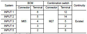
Does continuity exist? YES >> GO TO 2.
NO >> Repair harnesses or connectors.
2.CHECK INPUT 1 - 5 CIRCUIT FOR SHORT
Check for continuity between BCM harness connector and ground.
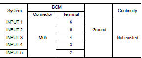
Does continuity exist? YES >> Repair harnesses or connectors.
NO >> GO TO 3.
3.CHECK BCM INPUT SIGNAL
1. Connect BCM and combination switch connectors.
2. Turn ON any switch in the system that is malfunction.
3. Check voltage between BCM harness connector and ground.
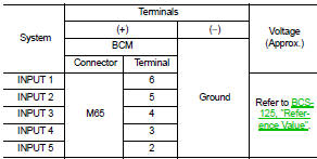
Is the measurement value normal? Yes >> Replace BCM. Refer to BCS-161, "Removal and Installation".
No >> Replace combination switch.
 Combination switch output circuit
Diagnosis Procedure
1.CHECK OUTPUT 1 - 5 CIRCUIT FOR OPEN
1. Turn ignition switch OFF.
2. Disconnect BCM and combination switch connectors.
3. Check continuity between BCM harness connector and co ...
 Symptom diagnosis
COMBINATION SWITCH SYSTEM SYMPTOMS
Symptom Table
1. Perform “Data Monitor” of CONSULT-III to check for any malfunctioning
item.
2. Check the malfunction combinations.
3. Identify the malfuncti ...
Other materials:
P0520 EOP sensor
DTC Logic
DTC CONFIRMATION PROCEDURE
1.PRECONDITIONING
If DTC Confirmation Procedure has been previously conducted, always perform
the following procedure
before conducting the next test.
1. Turn ignition switch OFF and wait at least 10 seconds.
2. Turn ignition switch ON.
3. Turn ignitio ...
U0140 lost communication (BCM)
Description
CAN (Controller Area Network) is a serial communication line for real-time
application. It is an on-vehicle multiplex
communication line with high data communication speed and excellent malfunction
detection ability.
Many electronic control units are equipped onto a vehicle, and ...
B1052, B1057 driver air bag module
DTC Logic
DTC DETECTION LOGIC
DTC CONFIRMATION PROCEDURE
1.CHECK SELF-DIAG RESULT
With CONSULT-III
1. Turn ignition switch ON.
2. Perform “Self Diagnostic Result” mode of “AIR BAG” using CONSULT-III.
Without CONSULT-III
1. Turn ignition switch ON.
2. Check the air bag warning lamp statu ...
