Nissan Juke Service and Repair Manual : Clutch fluid
RS5F92R : Inspection
FLUID LEAKAGE
• Check clutch line for cracks, deterioration or other damage. Replace any damaged parts.
• Check for fluid leakage by fully depressing clutch pedal while engine is running.
CAUTION:
If leakage occurs around joints, reinstall the joints or, if necessary, replace
damaged parts.
FLUID LEVEL
• Check that the fluid level in the reservoir tank is within the specified range (MAX – MIN lines).
• Visually check for any clutch fluid leakage around the reservoir tank.
• Check the clutch system for any leakage if the fluid level is extremely low (lower than MIN).
RS5F92R : Draining
CAUTION:
Keep painted surface on the body or other parts free of clutch fluid. If it
spills, wipe up immediately
and wash the affected area with water.
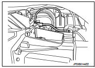
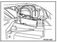
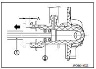
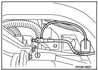
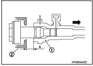
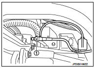
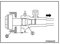
1. Connect a transparent vinyl hose to air bleeder of bleeding connector (1).
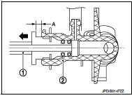
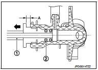
2. Press the lock pin (1) into the bleeding connector (2), and maintain the position.
3. Slide clutch tube (1) in the direction of the arrow as shown in the figure.
2 : Bleeding connector
Dimension “A” : 5 mm (0.20 in)
4. Depress clutch pedal to gradually discharge clutch fluid.
CAUTION:
Since the inside of clutch tube is under hydraulic pressure,
hold the tube to prevent it from getting disconnected.
RS5F92R : Refilling
CAUTION:
Keep painted surface on the body or other parts free of clutch fluid. If it
spills, wipe up immediately
and wash the affected area with water.
1. Check that there is no foreign material in reservoir tank, and then fill with new clutch fluid.
CAUTION:
Never reuse drained clutch fluid
.
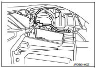
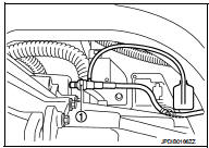
2. Connect a transparent vinyl hose to air bleeder of bleeding connector (1).
3. Press the lock pin (1) into the bleeding connector (2), and maintain the position.
4. Slide clutch tube (1) in the direction of the arrow as shown in the figure.
2 : Bleeding connector
Dimension “A” : 5 mm (0.20 in)
5. Slowly depress clutch pedal to the full stroke position, and then release the pedal.
CAUTION:
Since the inside of clutch tube is under hydraulic pressure,
hold the tube to prevent it from getting disconnected.
6. Repeat step 5 at intervals of 2 or 3 seconds until new clutch fluid is discharged.
CAUTION:
Monitor clutch fluid level in reservoir tank so as not to empty the tank.
7. Return clutch tube and lock pin in their original positions while clutch pedal is depressed.
8. Perform the air bleeding. Refer to CL-12, "RS5F92R : Air Bleeding".
RS5F92R : Air Bleeding
CAUTION:
• Monitor clutch fluid level in reservoir tank so as not to empty the tank.
• Keep painted surface on the body or other parts free of clutch fluid. If it spills, wipe up immediately and wash the affected area with water.
NOTE:
Do not use a vacuum assist or any other type of power bleeder on this system. Use of a vacuum assist or power bleeder will not purge all the air from the system.
1. Fill reservoir tank with new clutch fluid.
CAUTION:
Never reuse drained clutch fluid.
2. Connect a transparent vinyl hose to air bleeder of bleeding connector (1).
3. “Depress” and “release” the clutch pedal slowly and fully 15 times at an interval of 2 to 3 seconds and release the clutch pedal.
4. Press the lock pin (1) into the bleeding connector (2), and maintain the position.
CAUTION:
Since the inside of clutch tube is under hydraulic pressure,
hold the tube to prevent it from getting disconnected.
5. Slide clutch tube (1) in the direction of the arrow as shown in the figure.
2 : Bleeding connector
Dimension “A” : 5 mm (0.20 in)
6. Depress the clutch pedal soon and hold it, and then bleed the air from the piping.
CAUTION:
Since the inside of clutch tube is under hydraulic pressure,
hold the tube to prevent it from getting disconnected.
7. Return clutch tube and lock pin in their original positions.
8. Release clutch pedal and wait for 5 seconds.
9. Repeat steps 3 to 8 until no bubbles are observed in the clutch fluid.
10. Check that the fluid level in the reservoir tank is within the specified range after air bleeding. Refer to CL- 10, "RS5F92R : Inspection".
RS6F94R : Inspection
FLUID LEAKAGE
• Check clutch line for cracks, deterioration or other damage. Replace any damaged parts.
• Check for fluid leakage by fully depressing clutch pedal while engine is running.
CAUTION:
If leakage occurs around joints, reinstall the joints or, if necessary, replace
damaged parts
.
FLUID LEVEL
• Check that the fluid level in the reservoir tank is within the specified range (MAX – MIN lines).
• Visually check for any clutch fluid leakage around the reservoir tank.
• Check the clutch system for any leakage if the fluid level is extremely low (lower than MIN).
RS6F94R : Draining
CAUTION:
Keep painted surface on the body or other parts free of clutch fluid. If it
spills, wipe up immediately
and wash the affected area with water.
1. Connect a transparent vinyl hose to air bleeder of bleeding connector (1).
2. Press the lock pin (1) into the bleeding connector (2), and maintain the position.
3. Slide bleeding connector (1) in the direction of the arrow as shown in the figure.
2 : Clutch housing
Dimension “A” : 10 mm (0.39 in)
4. Depress clutch pedal to gradually discharge clutch fluid.
CAUTION:
Since the inside of clutch tube is under hydraulic pressure,
hold the tube to prevent it from getting disconnected.
RS6F94R : Refilling
CAUTION:
Keep painted surface on the body or other parts free of clutch fluid. If it
spills, wipe up immediately
and wash the affected area with water.
1. Check that there is no foreign material in reservoir tank, and then fill with new clutch fluid.
CAUTION:
Never reuse drained clutch fluid.
2. Connect a transparent vinyl hose to air bleeder of bleeding connector (1).
3. Press the lock pin (1) into the bleeding connector (2), and maintain the position.
4. Slide bleeding connector (1) in the direction of the arrow as shown in the figure.
2 : Clutch housing
Dimension “A” : 10 mm (0.39 in)
5. Slowly depress clutch pedal to the full stroke position, and then release the pedal.
CAUTION:
Since the inside of clutch tube is under hydraulic pressure,
hold the tube to prevent it from getting disconnected.
6. Repeat step 5 at intervals of 2 or 3 seconds until new clutch fluid is discharged.
CAUTION:
Monitor clutch fluid level in reservoir tank so as not to empty the tank.
7. Return clutch tube and lock pin in their original positions while clutch pedal is depressed.
8. Perform the air bleeding. Refer to CL-15, "RS6F94R : Air Bleeding".
RS6F94R : Air Bleeding
CAUTION:
• Monitor clutch fluid level in reservoir tank so as not to empty the tank.
• Keep painted surface on the body or other parts free of clutch fluid. If it spills, wipe up immediately and wash the affected area with water.
NOTE:
Do not use a vacuum assist or any other type of power bleeder on this system. Use of a vacuum assist or power bleeder will not purge all the air from the system.
1. Fill reservoir tank with new clutch fluid.
CAUTION:
Never reuse drained clutch fluid.
2. Connect a transparent vinyl hose to air bleeder of bleeding connector (1).
3. “Depress” and “release” the clutch pedal slowly and fully 15 times at an interval of 2 to 3 seconds and release the clutch pedal.
4. Press the lock pin (1) into the bleeding connector (2), and maintain the position.
CAUTION:
Since the inside of clutch tube is under hydraulic pressure,
hold the tube to prevent it from getting disconnected.
5. Slide bleeding connector (1) in the direction of the arrow as shown in the figure.
2 : Clutch housing
Dimension “A” : 10 mm (0.39 in)

6. Depress the clutch pedal soon and hold it, and then bleed the air from the piping.
CAUTION:
Since the inside of clutch tube is under hydraulic pressure,
hold the tube to prevent it from getting disconnected.
7. Return clutch tube and lock pin in their original positions.
8. Release clutch pedal and wait for 5 seconds.
9. Repeat steps 3 to 8 until no bubbles are observed in the clutch fluid.
10. Check that the fluid level in the reservoir tank is within the specified range after air bleeding. Refer to CL- 13, "RS6F94R : Inspection".
 Clutch pedal
Inspection and Adjustment
INSPECTION
The Height of Clutch Pedal
1. Turn the floor carpet.
2. Check that the clutch pedal height “H1” from the dash lower
panel (1) is within the reference value.
...

Other materials:
Front wheel hub and knuckle
Exploded View
1. Steering knuckle
2. Splash guard
3. Hub bolt
4. Wheel hub assembly (Bearing-integrated
type)
5. Disc rotor
6. Wheel hub lock nut
7. Adjusting cap
8. Cotter pin
A. Tightening must be done following the installation procedure. Refer to
FAX-11, "Removal and Insta ...
Air breather hose
MR16DDT : Exploded View
1. Clip
2. Air breather hose
3. 2 way connector
MR16DDT : Removal and Installation
REMOVAL
1. Remove air cleaner case. Refer to EM-26, "Removal and Installation".
2. Remove clips (1).
: Vehicle front
3. Remove air breather hose from the 2 way connector. ...
Oil pump
Exploded View
1. Oil pump drive chain
2. Crankshaft sprocket
3. Oil pump assembly
Removal and Installation
REMOVAL
1. Disconnect the battery cable from the negative terminal.
2. Remove engine under cover.
3. Remove front wheel RH. Refer to WT-7, "Exploded View".
4. Remove fen ...
