Nissan Juke Service and Repair Manual : Center stem assembly
Exploded View
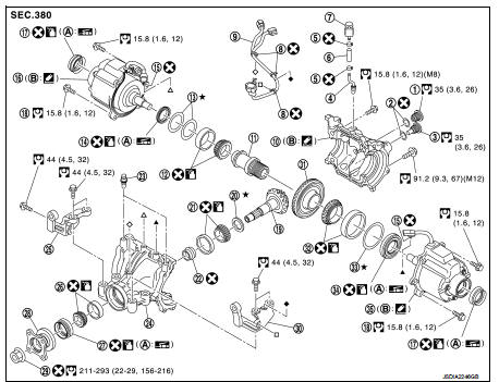
1. Filler plug
2. Gasket
3. Drain plug
4. Breather tube
5. Clip
6. Breather hose
7. Breather
8. sub-harness clip
9. sub-harness
10. Rear cover
11. Center stem
12. Side bearing (right)
13. Side bearing adjusting shim (right)
14. Side oil seal (right)
15. Connector clip
16. Electric controlled coupling (right)
17. Electric controlled coupling oil seal
18. Reamer bolt
19. Drive pinion
20. Drive pinion adjusting shim
21. Pinion rear bearing
22. Collapsible spacer
23. Breather
24. Gear carrier
25. Carrier bracket (right)
26. Pinion front bearing
27. Front oil seal
28. Companion flange
29. Drive pinion lock nut
30. Carrier bracket (left)
31. Drive gear
32. Side bearing (left)
33. Side bearing adjusting shim (left)
34. Electric controlled coupling (left)
35. Side oil seal (left)
A. Oil seal lip B. Gear carrier mounting face
 : N·m (kg-m, ft-lb)
 : Always replace after every
disassembly.
 : Apply gear oil.
 : Apply anti-corrosive oil.
 : Apply multi purpose grease
 : Apply Genuine Liquid Gasket 1217
or equivalent.
 : Select with proper thickness.
Disassembly
1. Remove carrier bracket.
2. Remove electric controlled coupling. Refer to DLN-147, "Disassembly".
3. Remove side oil seal. Refer to DLN-147, "Disassembly".
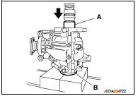
4. Remove rear cover mounting bolts.
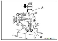
5. Set drifts (A and B) to the right and left side bearing adjusting shims individually. Press center stem assembly with side bearing to remove gear carrier assembly and rear cover assembly.
A : Drift (SST: KV38109820) B : Drift (SST: KV38109810)
CAUTION:
The pressure shall be as low as possible to remove gear
carrier assembly and rear cover assembly. The maximum
pressure shall be 10 kN (1 ton, 1.0 Imp ton).
NOTE:
Center stem assembly, side bearings, and adjusting shims are compressed and integrated in gear carrier and rear cover.
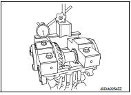
6. Remove drain plug and filler plug.
7. Remove side bearing adjusting shims and side bearing outer races.
CAUTION:
Mark the side bearing adjusting shims so that the original mounting positions
(right/left) can be
identified later.
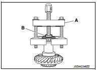
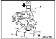
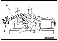
8. Remove side bearing inner race, using a puller (A) and drift (B).
A : Puller (commercial service tool) B : Drift (SST: ST33052000)
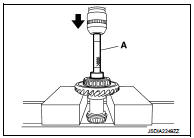
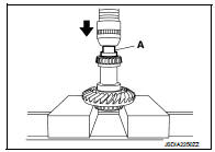
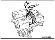
9. Remove drive gear from center stem, using a drift (A) (SST:ST33220000).
10. Perform inspection after diassembly. Refer to DLN-157, "Inspection".
Assembly
1. Press drive gear to center stem, using a drift (A) (SST:ST33052000).
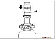
2. Press side bearing inner race to center stem assembly, using a drift (A) (SST: KV40104840).
3. Install new side bearing adjusting shims (2 pieces for one side) with the same thickness as the ones installed prior to disassembly or re-install the old ones, with side bearing outer race to center stem assembly.
If side bearing adjusting shims have been already selected, use them.
CAUTION:
• Never reuse side bearing outer race.
• Apply gear oil to side bearings.
4. Set drifts (A and B) to the right and left side bearing adjusting shims individually. Press center stem assembly with side bearing to install gear carrier to center stem assembly.
A : Drift (SST: KV38109820) B : Drift (SST: KV38109810)
CAUTION:
• The drift shall be placed on the center of the adjusting
shims.
• The pressure shall be as low as possible to install differential assembly into gear carrier assembly. The maximum pressure shall be 10 kN (1 ton, 1.0 Imp ton).
• If the adjusting shims are installed by tapping, the gear carrier may be damaged. Avoid tapping.
5. Install dummy cover set, check and adjust drive gear runout, tooth contact, backlash, and total preload torque. Refer to DLN-154, "Adjustment".
6. Remove dummy cover set.
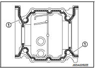
7. Apply liquid gasket (1) to mating surface of rear cover. Overlap both ends of the bead for at least 3 mm (0.12 in).
CAUTION:
Remove old gasket adhering to the mounting surfaces.
Also remove any moisture, oil, or foreign material adhering to the mounting surfaces.
8. Set the drifts (A and B) to the right and left side bearing adjusting shims individually. Compress center stem assembly and side bearing to install rear cover.
A : Drift (SST: KV38109820) B : Drift (SST: KV38109810)
CAUTION:
• The drift shall be placed on the center of the adjusting
shims.
• The pressure shall be as low as possible to install the rear cover. The maximum pressure shall be 10 kN (1 ton, 1.0 Imp ton).
• If rear cover is forced in by tapping, rear cover may be damaged by adjusting shims. Avoid tapping.
9. Tighten rear cover mounting bolts to the specified torque.
10. Install side oil seal. Refer to DLN-148, "Assembly".
11. Check total preload torque. Refer to DLN-154, "Adjustment".
Adjustment
TOTAL PRELOAD TORQUE
1. Remove electric controlled coupling assembly. Refer to DLN-147, "Disassembly".
2. Rotate drive pinion back and forth 2 to 3 times to check for unusual noise and rotation malfunction.
3. Rotate drive pinion at least 20 times to check for smooth operation of the bearing.
4. Measure the total preload, using the preload gauge (A) (SST: 3127S000).
Total preload torque : Refer to DLN-167, "Preload Torque".
NOTE:
Total preload torque = Pinion bearing torque + Side bearing
torque
• If measured value is out of the specification, disassemble it to check and adjust each part. Adjust the pinion bearing preload and side bearing preload.
Adjust the pinion bearing preload first, then adjust the side bearing preload.
When the preload torque is large On pinion bearings: Replace the collapsible spacer.
On side bearings: Use thinner side bearing adjusting shims.
When the preload is small On pinion bearings: Tighten the drive pinion nut.
On side bearings: Use thicker side bearing adjusting shims.
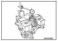
DRIVE GEAR RUNOUT
1. Remove rear cover. Refer to DLN-152, "Disassembly".
2. Following the procedure below, install a dummy cover set (SST: KV381096S0) to gear carrier.
a. Temporarily tighten bearing guides (SST: KV38109610, KV38109620) to gear carrier.
b. Position dummy cap spacers (SST: KV38109630, KV38109640) and angle (SST:KV38109650) to bearing guide.
c. Tighten rear cover mounting bolts to the specified torque. Refer to DLN-151, "Exploded View".
d. Tighten dummy cap spacer mounting bolts evenly to the specified torque.
Tightening torque : 5.9 N·m (0.6 kg-m, 52 in-lb)
3. Fit a dial indicator to the drive gear back face.
4. Rotate the drive gear to measure runout.
Drive gear back face runout : Refer to DLN-167, "Drive Gear Runout".
• If the runout is outside of the repair limit, check drive gear assembly condition; foreign material may be caught between drive gear and differential case, or differential case or drive gear may be deformed, etc.
CAUTION:
Replace drive gear and drive pinion as a set.
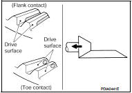
TOOTH CONTACT
1. Remove rear cover. Refer to DLN-152, "Disassembly".
2. Following the procedure below, install a dummy cover set (SST: KV381096S0) to gear carrier.
a. Temporarily tighten bearing guides (SST: KV38109610, KV38109620) to gear carrier.
b. Position dummy cap spacers (SST: KV38109630, KV38109640) and angle (SST:KV38109650) to bearing guide.
c. Tighten rear cover mounting bolts to the specified torque. Refer to DLN-151, "Exploded View".
d. Tighten dummy cap spacer mounting bolts evenly to the specified torque.
Tightening torque : 5.9 N·m (0.6 kg-m, 52 in-lb)
3. Apply red lead to drive gear.
CAUTION:
Apply red lead to both the faces of 3 to 4 gears at 4 locations
evenly spaced on drive gear.
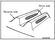
4. Rotate drive gear back and forth several times, check drive pinion gear to drive gear tooth contact.
CAUTION:
Check tooth contact on drive side and reverse side.
Tooth Contact Judgment Guide
5. If tooth contact is improperly adjusted, follow the procedure below to adjust the pinion height (dimension X).
• If the tooth contact is near the face (face contact), or near the heel (heel contact), thicken drive pinion gear adjusting shim to move drive pinion closer to drive gear.
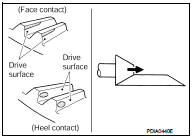
• If the tooth contact is near the flank (flank contact), or near the toe (toe contact), thin drive pinion gear adjusting shim to move drive pinion farther from drive gear.
BACKLASH
1. Remove rear cover. Refer to DLN-152, "Disassembly".
2. Following the procedure below, install a dummy cover set (SST: KV381096S0) to gear carrier.
a. Temporarily tighten bearing guides (SST: KV38109610, KV38109620) to gear carrier.
b. Position dummy cap spacers (SST: KV38109630, KV38109640) and angle (SST:KV38109650) to bearing guide.
c. Tighten rear cover mounting bolts to the specified torque. Refer to DLN-151, "Exploded View".
d. Tighten dummy cap spacer mounting bolts evenly to the specified torque.
Tightening torque : 5.9 N·m (0.6 kg-m, 52 in-lb)
3. Fit a dial indicator to the drive gear face to measure the backlash.
Backlash : Refer to DLN-167, "Backlash".
• If the backlash is outside of the specified value, change the thickness of side bearing adjusting shims.
When the backlash is large: Make drive gear back adjusting shims thicker, and drive gear front adjusting shims thinner.
When the backlash is small: Make drive gear back adjusting shims thinner, and drive gear front adjusting shims thicker.
Inspection
INSPECTION AFTER DISASSEMBLY
Drive Gear and Drive Pinion • Clean up the disassembled parts.
• If the gear teeth never mesh or line-up correctly, determine the cause and adjust or replace as necessary.
• If the gears are worn, cracked, damaged, pitted or chipped (by friction) noticeably, replace with new drive gear and drive pinion as a set.
Bearing
• Clean up the disassembled parts.
• If any chipped (by friction), pitted, worn, rusted or scratched marks, or unusual noise from the bearing is observed, replace as a bearing assembly (as a new set).
Oil Seal
• Whenever disassembled, replace.
• If wear, deterioration of adherence (sealing force lips), or damage is detected on the lips, replace them.
Companion Flange
• Clean up the disassembled parts.
• If any chipped mark [about 0.1 mm, (0.004 in)] or other damage on the contact sides of the lips of the companion flange is found, replace.
 Electric controlled coupling
Exploded View
1. Filler plug
2. Gasket
3. Drain plug
4. Breather tube
5. Clip
6. Breather hose
7. Breather
8. sub-harness clip
9. sub-harness
10. Rear cover
11. Center stem
12. S ...
 Drive pinion
Exploded View
1. Filler plug
2. Gasket
3. Drain plug
4. Breather tube
5. Clip
6. Breather hose
7. Breather
8. sub-harness clip
9. sub-harness
10. Rear cover
11. Center stem
12. S ...
Other materials:
Diagnosis system (navi control unit)
Diagnosis Description
On-Board Diagnosis Item
• On-board diagnosis is performed in service test mode.
• On-board diagnosis checks if the system operates normally.
Service test mode
METHOD OF STARTING
1. Start the engine.
2. Turn OFF audio.
3. While pressing the “SET UP” switch, turn th ...
Precaution for Supplemental Restraint System (SRS) "AIR BAG" and "SEAT BELT
PRE-TENSIONER"
The Supplemental Restraint System such as “AIR BAG” and “SEAT BELT PRE-TENSIONER”,
used along
with a front seat belt, helps to reduce the risk or severity of injury to the
driver and front passenger for certain
types of collision. This system includes seat belt switch inputs and dual stage
f ...
Air breather hose
MR16DDT : Exploded View
1. Clip
2. Air breather hose
3. 2 way connector
MR16DDT : Removal and Installation
REMOVAL
1. Remove air cleaner case. Refer to EM-26, "Removal and Installation".
2. Remove clips (1).
: Vehicle front
3. Remove air breather hose from the 2 way connector. ...
