Nissan Juke Service and Repair Manual : Catalyst
2WD
2WD : Exploded View
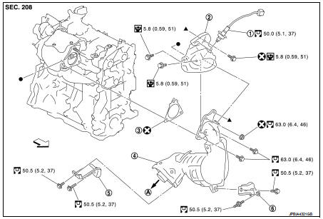
1. A/F sensor 1
2. Catalyst convertor shroud upper
3. Gasket
4. Catalyst
5. Catalyst convertor support bracket rear
6. Catalyst convertor bracket (RH)
A. To exhaust system
 : Engine front
 : N·m (kg-m, ft-lb)
 : N·m (kg-m, in-lb)
 : Always replace after every
disassembly.
2WD : Removal and Installation
REMOVAL
1. Remove engine cover. Refer to EM-25, "Exploded View".
2. Remove cowl top extension. Refer to EXT-20, "Exploded View".
3. Remove front tube. Refer to EX-5, "Exploded View".
4. Remove A/F sensor 1.
• Using heated oxygen sensor wrench [SST: KV10117100], remove A/F sensor 1.
CAUTION:
Handle A/F sensor 1 carefully and avoid impacts.
5. Remove catalyst convertor shroud upper.
6. Remove bolts and nut of catalyst convertor turbocharger side.
7. Remove support bracket (RH).
8. Remove drive shaft insulator. Refer to 9. Remove catalyst convertor.
INSTALLATION
1. Install catalyst convertor with the following procedure.
• Tighten in numerical order as shown in the figure.
- Install catalyst convertor (base on stud position 1).
- Temporary assemble 2 (no priority).
- Temporary assemble 3, 4.
- Tightening 5, 6 and 7.
- Tightening again 8, 9 and 10.
- Temporary assemble 11.
- Tightening 12,13,14,and 15.
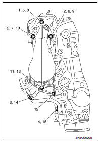
2. Install in the reverse order of removal after this step.
4WD
4WD : Exploded View
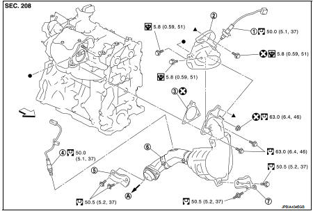
1. A/F sensor 1
2. Catalyst convertor shroud upper
3. Gasket
4. Heated oxygen sensor 2
5. Catalyst convertor upport bracket rear
6. Catalyst convertor
7. Catalyst convertor support bracket (RH)
A. To exhaust system
Engine front
: N·m (kg-m, ft-lb)
: N·m (kg-m, in-lb)
: Always replace after every
disassembly.
4WD : Removal and Installation
REMOVAL
1. Drain engine coolant. Refer to CO-11, "Draining".
2. Remove engine cover. Refer to EM-25, "Exploded View".
3. Remove cowl top extension. Refer to EXT-20, "Exploded View".
4. Remove front tube. Refer to EX-5, "Exploded View" 5. Remove A/F sensor 1.
6. Remove catalyst convertor shroud upper.
7. Remove bolts and nut of catalyst convertor turbocharger side.
8. Remove drive shaft insulator.
9. Remove support bracket (RH).
10. Move catalyst convertor.
11. Remove turbocharger. Refer to EM-36, "Exploded View".
12. Remove catalyst convertor.
INSTALLATION
1. Install catalyst convertor with the following procedure.
• Tighten in numerical order as shown in the figure.
- Install catalyst convertor (base on stud position 1).
- Temporary assemble 2 (no priority).
- Temporary assemble 3, 4.
- Tightening 5, 6 and 7.
- Tightening again 8, 9 and 10.
- Temporary assemble 11.
- Tightening 12,13,14,and 15.
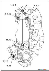
2. Install in the reverse order of removal after this step.
 Charge air cooler
Exploded View
1. Air inlet tube assembly
2. Air inlet tube bracket
3. Clamp
4. Air inlet hose
5. Gasket
6. Turbocharger
7. Mounting rubber
8. Charge air cooler
9. Air inlet tube assem ...
 Turbocharger
Exploded View
1. Heat insulator
2. Actuator hose
3. Clamp
4. Turbocharger inlet tube
5. Gasket
6. Gasket
7. Clamp
8. Oil outlet hose
9. Oil return pipe
10. Oil supply tube
11. O-ri ...
Other materials:
Precaution Necessary for Steering Wheel Rotation after Battery Disconnect
NOTE:
• Before removing and installing any control units, first turn the ignition
switch to the LOCK position, then disconnect
both battery cables.
• After finishing work, confirm that all control unit connectors are connected
properly, then re-connect both
battery cables.
• Always use CONS ...
Shift P warning lamp
Component Function Check
1.CHECK FUNCTION
1. Select “INTELLIGENT KEY” of “BCM” using CONSULT-III.
2. Select “LCD” in “ACTIVE TEST” mode.
3. Check that the function operates normally according to the following
conditions.
Is the inspection result normal?
YES >> Shift P warning lamp is ...
ANTI-HIJACK function does not operate
Diagnosis Procedure
1.CHECK “DOOR LOCK–UNLOCK SET” SETTING IN “WORK SUPPORT”
1. Select “DOOR LOCK” of “BCM” using CONSULT-III.
2. Select “DOOR LOCK-UNLOCK SET” in “WORK SUPPORT” mode.
3. Check “DOOR LOCK-UNLOCK SET” in “WORK SUPPORT”
Refer to DLK-501, "DOOR LOCK : CONSULT-III Function (BCM ...
