Nissan Juke Service and Repair Manual : Camshaft
Exploded View
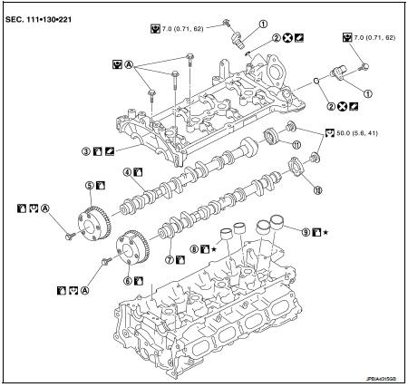
1. Camshaft position sensor (PHASE)
2. O-ring
3. Camshaft bracket
4. Camshaft (EXH)
5. Camshaft sprocket (EXH)
6. Camshaft sprocket (INT)
7. Camshaft (INT)
8. Valve lifter (EXH)
9. Valve lifter (INT)
10. Signal plate (INT)
11 Signal plate (EXH)
A.Tightening must be done following the installation procedure.
Refer to EM-79
 : N·m (kg-m, ft-lb)
 : N·m (kg-m, in-lb)
 : Always replace after every
disassembly.
 : Should be lubricated with oil.
 : Sealing point
 : Select with proper thickness.
Removal and Installation
CAUTION:
The rotating direction in the text indicates all directions seen from the engine
front.
REMOVAL
1. Remove the following parts.
• Intake manifold: Refer to EM-28, "Exploded View".
• Rocker cover: Refer to EM-23, "Exploded View".
• Front cover and timing chain related parts: Refer to EM-67, "Exploded View".
NOTE
:
Removal of oil pump drive related part is not necessary.
2. Remove camshaft position sensor (PHASE) from camshaft bracket.
CAUTION:
• Handle camshaft position sensor (PHASE) carefully and avoid impacts.
• Never disassemble camshaft position sensor (PHASE).
• Never place sensor where it is exposed to magnetism.
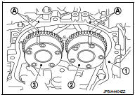
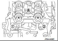
3. Put the matching mark (A) on the camshaft sprocket (INT) (1), camshaft sprocket (EXH) (2) and the camshaft bracket (1) as shown in the figure.
NOTE
:
It prevents the knock pin of the camshaft (INT) from engaging
with the incorrect pin hole when installing the camshaft sprocket
(INT).
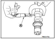
4. Remove camshaft sprockets (INT and EXH).
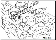
• Secure hexagonal part (A) of camshaft with a wrench. Loosen camshaft sprocket mounting bolts and remove camshaft sprocket.
1 : Camshaft sprocket (INT) 2 : Camshaft sprocket (EXH)
CAUTION:
• Never rotate crankshaft or camshaft while timing chain
is removed. It causes interference between valve and
piston.
• Never loosen the mounting bolts with securing anything other than the camshaft hexagonal part or with tensioning the timing chain.
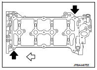
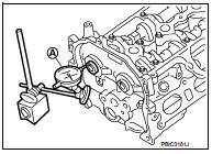
5. Remove camshaft bracket with the following procedure: a. Loosen mounting bolts in reverse order as shown in the figur
 : Engine front
b. Cut liquid gasket by prying the position (
) shown in the figure,
and then remove the camshaft bracket.
: Engine front
CAUTION:
• Be careful not to damage the mating surface.
• A more adhesive liquid gasket is applied compared to previous types when shipped, so it should not be forced off the position not specified.
6. Remove camshafts.
7. Remove valve lifters.
• Identify installation positions, and store them without mixing them up.
8. Remove signal plate from camshaft, if necessary.
INSTALLATION
1. Install valve lifters.
• Install them in the original positions.
2. Install camshafts.
• Clean camshaft journal to remove any foreign material.
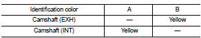
• Distinguish between the intake and the exhaust by looking at the different shapes of the front and rear ends of the camshaft or using the identification colors (A) and (B).
1 : Camshaft (EXH)
2 : Camshaft (INT)
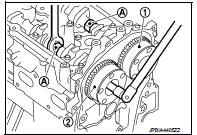
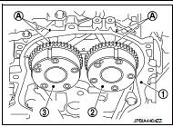
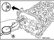
• Install camshafts so that camshaft dowel pins (A) on the front side are positioned as shown in the figure.
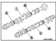
1 : Camshaft (EXH)
2 : Camshaft (INT)
NOTE
: Though camshaft does not stop at the positions as shown in the figure, for the placement of cam nose, it is generally accepted camshaft is placed for the same direction of the figure.
3. Install camshaft bracket with the following procedure: a. Remove foreign material completely from camshaft bracket backside and from cylinder head installation face.
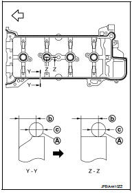
b. Apply liquid gasket (A) to camshaft bracket as shown in the figure.
b : Plug hole inner wall
c : 3.4 - 4.4mm (0.134 - 0.173 in)
 : Engine front
 : Engine outside
Use Genuine Liquid Gasket or equivalent.
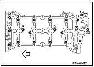
c. Tighten mounting bolts of camshaft brackets in the following steps, in numerical order as shown in the figure.
 : Engine front
• There are two types of mounting bolts. Refer to the following for locating bolts.
M6 bolts [thread length: 57.5 mm (2.264 in)] : 13, 14, and 15 in the figure M6 bolts [thread length: 35.0 mm (1.378 in)] : Except the above
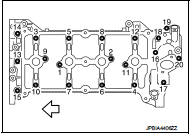
i. Tighten mounting bolts in numerical order.
 : 1.96 N·m (0.20 kg-m, 17 in-lb)
ii. Tighten mounting bolts in numerical order.
 : 5.88 N·m (0.60 kg-m, 52 in-lb)
iii. Tighten mounting bolts in numerical order.
 : 9.5 N·m (0.97 kg-m, 84 in-lb)
CAUTION:
After tightening mounting bolts of camshaft brackets, be sure to wipe off
excessive liquid gasket
from the mating surface of cylinder head.
4. Install the camshaft sprocket (INT) to the camshaft (INT) with the following procedure.
a. When the camshaft sprocket (INT) (2) and camshaft sprocket (EXH) (3) is removed, refer to the paint mark (A) put according to step “3”. Securely align the knock pin and the pin hole, and then install them.
1 : Camshaft bracket
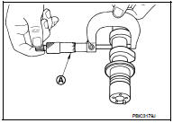
b. Tighten bolts in the following steps.
• Secure the hexagonal part of camshaft (INT) using wrench to tighten mounting bolt.
i. Tighten camshaft (INT) mounting bolt.
 : 35.0 N·m (3.6 kg-m, 26 ft-lb)
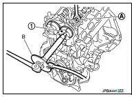
ii. Turn 67 degrees clockwise (angle tightening).
CAUTION:
Check the tightening angle by using an angle wrench [SST:
KV10112100 (BT8653-A)] (B) or protractor. Never judge by
visual inspection without an angle wrench.
1 : Camshaft sprocket (INT) A : Camshaft (INT) hexagonal part
5. Install timing chain and related parts. Refer to EM-67, "Exploded View".
6. Inspect and adjust valve clearance. Refer to EM-14, "Inspection and Adjustment".
7. Install remaining parts in the reverse order of removal.
Inspection
INSPECTION AFTER REMOVAL
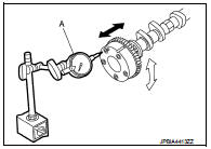
Camshaft Runout
1. Put V-block on a precise flat table, and support No. 2 and 5 journal of
camshaft.
CAUTION:
Never support No. 1 journal (on the side of camshaft sprocket) because it has a
different diameter
from the other four locations.
2. Set dial indicator (A) vertically to No. 3 journal.
3. Turn camshaft to one direction with hands, and measure the camshaft runout on dial indicator. (Total indicator reading)
Standard and Limit : Refer to EM-130, "Camshaft".
4. If it exceeds the limit, replace camshaft.
Camshaft Cam Height
1. Measure the camshaft cam height with a micrometer (A).
Standard and Limit : Refer to EM-130, "Camshaft".
2. If it exceeds the limit, replace camshaft.
Camshaft Journal Oil Clearance CAMSHAFT JOURNAL OUTER DIAMETER Measure the outer diameter of camshaft journal with a micrometer (A).
Standard : Refer to EM-130, "Camshaft".
CAMSHAFT BRACKET INNER DIAMETER
• Tighten camshaft bracket bolts with specified torque. Refer to EM-79, "Removal and Installation".
• Measure the inner diameter of camshaft bracket with a bore gauge (A).
B : Measuring direction of inner diameter
Standard : Refer to EM-130, "Camshaft".
CAMSHAFT JOURNAL OIL CLEARANCE
• (Oil clearance) = (Camshaft bracket inner diameter) – (Camshaft journal diameter)
Standard and Limit : Refer to EM-130, "Camshaft".
• If it exceeds the limit, replace camshaft or cylinder head, or both.
NOTE
:
Camshaft bracket cannot be replaced as a single part, because it is machined
together with cylinder head.
Replace whole cylinder head assembly.
Camshaft End Play
1. Install camshaft in cylinder head. Refer to EM-79, "Removal and
Installation".
2. Install dial indicator in thrust direction on front end of camshaft.
Read the end play of dial indicator (A) when camshaft is moved forward/backward (in direction to axis).
Standard and Limit : Refer to EM-130, "Camshaft".
• Measure the following parts if out of the standard.
- Dimension (A) for groove of cylinder head No. 1 journal
Standard : 4.000 - 4.030 mm (0.1575 - 0.1587 in)
- Dimension (B) for camshaft flange
Standard : 3.877 - 3.925 mm (0.1526 - 0.1545 in)
• Refer to the standards above, and then replace camshaft and/ or cylinder head.
Camshaft Sprocket Runout 1. Put V-block on precise flat table, and support No. 2 and 5 journals of camshaft.
CAUTION:
Never support No. 1 journal (on the side of camshaft sprocket) because it has a
different diameter
from the other four locations.
2. Measure the camshaft sprocket runout with a dial indicator (A).
(Total indicator reading)
Limit : Refer to EM-130, "Camshaft".
• If it exceeds the limit, replace camshaft sprocket.
Valve Lifter
Check if surface of valve lifter has any wear or cracks.
• If anything above is found, replace valve lifter. Refer to EM-130, "Camshaft".
Valve Lifter Clearance
VALVE LIFTER OUTER DIAMETER
• Measure the outer diameter of valve lifter with a micrometer (A).
Standard : Refer to EM-130, "Camshaft".
VALVE LIFTER HOLE DIAMETER
Measure the inner diameter of valve lifter hole of cylinder head with an inside micrometer (A).
Standard : Refer to EM-130, "Camshaft".
VALVE LIFTER CLEARANCE
• (Valve lifter clearance) = (Valve lifter hole diameter) – (Valve lifter outer diameter)
Standard : Refer to EM-130, "Camshaft".
• If out of the standard, referring to the each standard of valve lifter outer diameter and valve lifter hole diameter, replace either or both valve lifter and cylinder head.
INSPECTION AFTER INSTALLATION
Inspection of Camshaft Sprocket (INT) Oil Groove
CAUTION:
• Perform this inspection only when DTC P0011 is detected in self-diagnostic
results of CONSULT-III
and it is directed according to inspection procedure of EC section. Refer to
EC-163, "Diagnosis Procedure".
• Check when engine is cold so as to prevent burns by the splashing engine oil.
1. Check engine oil level. Refer to LU-8, "Inspection".
2. Perform the following procedure so as to prevent the engine from being unintentionally started while checking.
a. Release the fuel pressure. Refer to EC-140, "Work Procedure".
b. Remove intake manifold. Refer to EM-28, "Exploded View".
c. Disconnect ignition coil and injector harness connectors.
d. Support the bottom surface of engine using a transmission jack, and then remove the engine mounting bracket (RH) and engine mounting insulator (RH). Refer to EM-55, "2WD : Exploded View".
3. Remove intake valve timing control solenoid valve. Refer to EM-67, "Exploded View".
• Lift the front side of the engine with a jack base to remove intake valve timing control solenoid valve.
4. Clean the mounting area of intake valve timing control solenoid valve, and then insert a clean waste with no oil adhesion into the oil hole of the cylinder head.
5. Install engine mounting insulator (RH) and engine mounting bracket (RH).
(After the removal of intake
valve timing control solenoid valve and insertion of a waste into the oil
hole.)
6. Perform cranking to check that engine oil comes out from the oil hole
(mounting hole of intake valve timing
control solenoid valve) of cylinder head.
• Regarding the engine oil check, judge it by the amount of oil adhered to the wasted inserted into the oil hole.
WARNING:
• Never insert fingers into the oil hole.
• Be careful not to touch rotating parts (drive belt, idler pulleys and crankshaft pulley, etc.).
CAUTION:
• Never perform cranking without installing the engine mounting insulator (RH)
and engine mounting
bracket (RH).
• Prevent splashing by using a shop cloth so as to prevent the worker from injury from engine oil and so as to prevent engine oil contamination.
• Prevent splashing by using a shop cloth so as to prevent engine oil from being splashed to engine and vehicle. Especially, be careful not to apply engine oil to rubber parts of drive belt, engine mounting insulator, etc. Wipe engine oil off immediately if it is splashed.
7. Perform the following inspection if engine oil does not come out from intake valve timing control solenoid valve oil hole of the cylinder head.
• Remove oil filter (for intake valve timing control), and then clean it. Refer to EM-103, "Exploded View".
• Clean oil groove between oil strainer and intake valve timing control solenoid valve. Refer to LU-3, "Engine Lubrication System" and LU-3, "Engine Lubrication System Schematic".
8. Remove components between intake valve timing control solenoid valve and camshaft sprocket (INT), and then check each oil groove for clogging.
• Clean oil groove if necessary. Refer to LU-3, "Engine Lubrication System" and LU-3, "Engine Lubrication System Schematic".
9. After inspection, install removed parts in the reverse order.
 Timing chain
Exploded View
1. Timing chain slack guide
2. Timing chain tensioner
3. Timing chain
4. Oil pump drive chain
5. Crankshaft sprocket
6. Crankshaft key
7. Oil pump sprocket
8. Front cover ...
 Oil seal
...
Other materials:
S terminal circuit
Description
The output voltage of the alternator is controlled by the IC voltage
regulator at the “S” terminal detecting the
input voltage.
The “S” terminal circuit detects the battery voltage to adjust the alternator
output voltage with the IC voltage
regulator.
Diagnosis Procedure
1.CH ...
Idle speed
Description
This describes how to check the idle speed. For the actual procedure, follow
the instructions in “BASIC
INSPECTION”.
Special Repair Requirement
1.CHECK IDLE SPEED
With CONSULT-III
Check idle speed in “DATA MONITOR” mode with CONSULT-III.
With GST
Check idle speed with Servic ...
CVT fluid
Replacement
CVT fluid : Refer to TM-512, "General Specification".
Fluid capacity : Refer to TM-512, "General Specificatio
CAUTION:
• Use only Genuine NISSAN CVT Fluid NS-2. Using transmission fluid other than
Genuine NISSAN
CVT Fluid NS-2 will damage the CVT, which is not cover ...
