Nissan Juke Service and Repair Manual : C1142 press sensor
DTC Logic
DTC DETECTION LOGIC
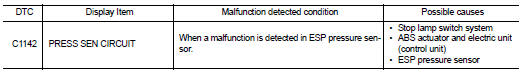
DTC CONFIRMATION PROCEDURE
1.PRECONDITIONING
If “DTC CONFIRMATION PROCEDURE” has been previously conducted, always turn ignition switch OFF and wait at least 10 seconds before conducting the next test.
>> GO TO 2.
2.CHECK DTC DETECTION
 With CONSULT-III.
1. Turn the ignition switch OFF to ON.
2. Perform self-diagnosis for “ABS”.
Is DTC “C1142” detected? YES >> Proceed to BRC-186, "Diagnosis Procedure".
NO >> INSPECTION END
Diagnosis Procedure
1.CHECK ABS ACTUATOR AND ELECTRIC UNIT (CONTROL UNIT) POWER SUPPLY SYSTEM
Check ABS actuator and electric unit (control unit) power supply system. Refer to BRC-205, "Diagnosis Procedure".
Is the inspection result normal? YES >> GO TO 2.
NO >> Repair or replace error-detected parts.
2.CHECK BRAKE FLUID LEACKAGE
Check brake fluid leakage.
• LHD: Refer to BR-12, "Inspection".
• RHD: Refer to BR-80, "Inspection".
Is the inspection result normal? YES >> GO TO 3.
NO >> Repair or replace error-detected parts.
3.CHECK CONNECTOR
1. Turn ignition switch OFF.
2. Check ABS actuator and electric unit (control unit) harness connector for disconnection or looseness.
3. Check ESP pressure sensor harness connector for disconnection or looseness.
Is the inspection result normal? YES >> GO TO 4.
NO >> Repair or replace error-detected parts, securely lock the connector, and GO TO 4.
4.PERFORM SELF-DIAGNOSIS
Perform self-diagnosis for “ABS” again.
Is DTC“C1142” detected? YES >> GO TO 5.
NO >> INSPECTION END 5.CHECK ESP PRESSURE SENSOR CIRCUIT
1. Turn ignition switch OFF.
2. Disconnect ABS actuator and electric unit (control unit) harness connector.
3. Disconnect ESP pressure sensor harness connector.
4. Check continuity between ESP pressure sensor harness connector and ABS actuator and electric unit (control unit) harness connecto
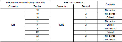
Is the inspection result normal? YES >> GO TO 6.
NO >> Repair or replace error-detected parts.
6.CHECK ESP PRESSURE SENSOR POWER SUPPLY
1. Connect ABS actuator and electric unit (control unit) harness connector.
2. Turn the ignition switch ON.
CAUTION:
Never start the engine.
3. Check voltage ESP pressure sensor harness connector terminals.
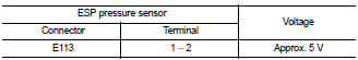
Is the inspection result normal? YES >> GO TO 7.
NO >> Replace ABS actuator and electric unit (control unit). Refer to BRC-233, "Removal and Installation".
7.CHECK ESP PRESSURESENSOR (1)
1. Turn ignition switch OFF.
2. Secure connect ESP pressure sensor harness connector.
3. Check loose connection with harness connector.
4. Turn ignition switch ON.
CAUTION:
Never start the engine.
5. In 1 second or more after ignition switch ON, check pressure sensor voltage.
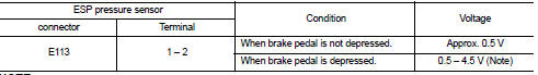
NOTE:
Voltage changes according to the degree of the application of the brake pedal.
Is the inspection result normal? YES >> Replace ABS actuator and electric unit (control unit). Refer to BRC-233, "Removal and Installation".
NO >> Replace ESP pressure sensor.
• LHD: Refer to BR-24, "FRONT : Exploded View".
• RHD: Refer to BR-91, "FRONT : Exploded View".
 C1140 actuator relay system
DTC Logic
DTC DETECTION LOGIC
DTC CONFIRMATION PROCEDURE
1.PRECONDITIONING
If “DTC CONFIRMATION PROCEDURE” has been previously conducted, always turn
ignition switch OFF and
wait at least 10 ...
 C1143 steering angle sensor
DTC Logic
DTC DETECTION LOGIC
DTC CONFIRMATION PROCEDURE
1.PRECONDITIONING
If “DTC CONFIRMATION PROCEDURE” has been previously conducted, always turn
ignition switch OFF and
wait at least 10 ...
Other materials:
Combination meter
Reference Value
VALUES ON THE DIAGNOSIS TOOL
NOTE:
Some items are not available according to vehicle specification.
TERMINAL LAYOUT
PHYSICAL VALUES
Fail-Safe
FAIL-SAFE
The combination meter activates the fail-safe control if CAN communication
with each unit is malfuncti ...
Precaution for Supplemental Restraint System (SRS) "AIR BAG" and "SEAT BELT
PRE-TENSIONER"
The Supplemental Restraint System such as “AIR BAG” and “SEAT BELT PRE-TENSIONER”,
used along
with a front seat belt, helps to reduce the risk or severity of injury to the
driver and front passenger for certain
types of collision. Information necessary to service the system safely is
include ...
Engine bucking
Description
CHART 9: ENGINE BUCKING
Diagnosis Procedure
1.CHECK ECM POWER SUPPLY AND GROUND CIRCUIT
Check ECM power supply and ground circuit. Refer to EC-885, "Diagnosis
Procedure".
Is the inspection result normal?
YES >> GO TO 2.
NO >> Repair or replace harness o ...
