Nissan Juke Service and Repair Manual : Brake pedal position switch
Component Function Check
1.CHECK BRAKE PEDAL POSITION SWITCH FUNCTION
 With CONSULT-III
1. Turn ignition switch ON.
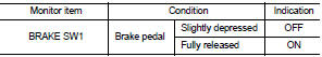
2. Select “BRAKE SW1” in “DATA MONITOR” mode of “ENGINE” using CONSULT-III.
3. Check “BRAKE SW1” indication as per the following conditions.
 Without CONSULT-III
1. Turn ignition switch ON.
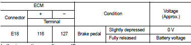
2. Check the voltage between ECM harness connector terminals as per the following.
Is the inspection result normal? YES >> INSPECTION END
NO >> Proceed to EC-425, "Diagnosis Procedure".
Diagnosis Procedure
1.CHECK BRAKE PEDAL POSITION SWITCH POWER SUPPLY
1. Turn ignition switch OFF.
2. Disconnect brake pedal position switch harness connector.
3. Turn ignition switch ON.
4. Check the voltage between brake pedal position switch harness connector and ground.
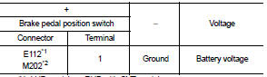
*1: LHD models or RHD with CVT models *2: RHD with M/T models
Is the inspection result normal? YES >> GO TO 2.
NO >> Perform the trouble diagnosis for power supply circuit.
2.CHECK BRAKE PEDAL POSITION SWITCH INPUT SIGNAL CIRCUIT
1. Turn ignition switch OFF.
2. Disconnect ECM harness connector.
3. Check the continuity between brake pedal position switch harness connector and ECM harness connector.
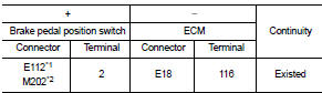
*1: LHD models or RHD with CVT models *2: RHD with M/T models
4. Also check harness for short to ground and to power.
Is the inspection result normal? YES >> GO TO 3.
NO >> Repair or replace error-detected parts.
3.CHECK BRAKE PEDAL POSITION SWITCH
Check the brake pedal position switch. Refer to EC-426, "Component Inspection (Brake Pedal Position Switch)" Is the inspection result normal? YES >> Check intermittent incident. Refer to GI-42, "Intermittent Incident".
NO >> Replace brake pedal position switch. Refer to BR-20, "Exploded View" (LHD) or BR-88, "Exploded View" (RHD)
Component Inspection (Brake Pedal Position Switch)
1.CHECK BRAKE PEDAL POSITION SWITCH-I
1. Turn ignition switch OFF.
2. Disconnect brake pedal position harness connector.
3. Check the continuity between brake pedal position switch terminals as per the following conditions.
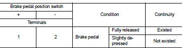
Is the inspection result normal? YES >> INSPECTION END
NO >> GO TO 2.
2.CHECK BRAKE PEDAL POSITION SWITCH-II
1. Adjust brake pedal position switch installation. Refer to BR-9, "Inspection and Adjustment" (LHD) or BR- 77, "Inspection and Adjustment" (RHD).
2. Check the continuity between brake pedal position switch terminals as per the following conditions.
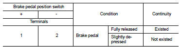
Is the inspection result normal? YES >> INSPECTION END
NO >> Replace brake pedal position switch. Refer to BR-20, "Exploded View" (LHD) or BR-88, "Exploded View" (RHD).
 Refrigerant pressure sensor
Component Function Check
1.CHECK REFRIGERANT PRESSURE SENSOR OVERALL FUNCTION
1. Start engine and warm it up to normal operating temperature.
2. Turn A/C switch and blower fan switch ON.
3. Check ...
 Clutch pedal position switch
Component Function Check
1.CHECK FOR CLUTCH PEDAL POSITION SWITCH FUNCTION
1. Turn ignition switch ON.
2. Check the voltage between ECM harness connector and ground.
Is the inspection result nor ...
Other materials:
U1001 Can comm circuit
Description
CAN (Controller Area Network) is a serial communication line for real time
application. It is an on-vehicle multiplex
communication line with high data communication speed and excellent error
detection ability. Many electronic
control units are equipped onto a vehicle, and each c ...
Outside mirror
Exploded View
1. Door mirror cover
2. Actuator
3. Glass mirror
4. Door mirror corner cover
5. Door mirror assembly
: Clip
: Pawl
Door mirror assembly
DOOR MIRROR ASSEMBLY : Removal and Installation
CAUTION:
When removing, always use a remover tool that is made of plastic.
REMOVAL
1 ...
Line pressure test
Work Procedure
INSPECTION
1. Check the engine oil level. Replenish if necessary. LU-25, "Inspection".
2. Check for leak of the CVT fluid. Refer to TM-480, "Inspection".
3. Drive for about 10 minutes to warm up the vehicle so that the CVT fluid
temperature is 50 to 80°C (122 ...
