Nissan Juke Service and Repair Manual : Brake master cylinder
Exploded View
2WD
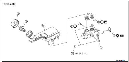
1. Reservoir cap
2. Oil strainer
3. Reservoir tank
4. Cylinder body
5. O-ring
6. Grommet
7. Pin
 : Apply polyglycol ether
lubricant
 : Apply brake fluid.
 : N·m (kg-m, ft-lb)
 : Always replace after every
disassembly.
4WD
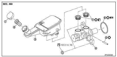
1. Reservoir cap
2. Oil strainer
3. Reservoir tank
4. Cylinder body
5. Pin
6. O-ring
7. Grommet
: Apply polyglycol ether
lubricant
: Apply brake fluid.
: N·m (kg-m, ft-lb)
: Always replace after every
disassembly.
Removal and Installation
REMOVAL
CAUTION:
• Never spill or splash brake fluid on painted surfaces. Brake fluid may
seriously damage paint. Wipe it
off immediately and wash with water if it gets on a painted surface. For brake
component parts,
never wash them with water.
• Never depress the brake pedal while removing the brake tube. If this is not complied with, brake fluid may splash.
1. Perform inspection before removal. Refer to BR-110, "Inspection".
2. Depress the brake pedal several times to release the vacuum pressure from the brake booster.
3. Drain brake fluid. Refer to BR-80, "Draining".
4. Disconnect the brake fluid level switch harness connector.
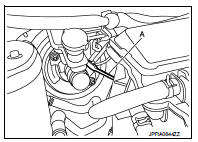
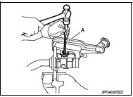
5. Separate the brake tube from master cylinder assembly with a flare nut wrench (A).
CAUTION:
Never scratch the flare nut and the brake tube.
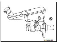
6. Remove the master cylinder assembly.
CAUTION:
• Never deform or bend the brake tubes.
• Never depress the brake pedal after the master cylinder assembly is removed.
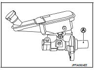
• The piston (A) of the master cylinder assembly is exposed. Never damage it when removing the master cylinder.
• The piston may drop off when pulled out strongly. Never hold the piston. Hold the cylinder body when handling the master cylinder assembly.
7. Remove the O-ring.
INSTALLATION
Note the following, and install in the reverse order of removal.
• Never spill or splash brake fluid on painted surfaces. Brake fluid may seriously damage paint. Wipe it off immediately and wash with water if it gets on a painted surface. For brake component parts, never wash them with water.
• Never depress the brake pedal while removing the brake tube. If this is not complied with, brake fluid may splash.
• Never depress the brake pedal after the master cylinder assembly is removed.
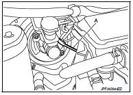
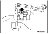
• Apply polyglycol ether based lubricant to the brake booster [see (A) in the figure] when installing the master cylinder assembly to the brake booster.
• The piston (A) of the master cylinder assembly is exposed. Never damage it when handling the master cylinder.
• Check that no dirt and dust are present on the piston before installation.
Clean it with new brake fluid if necessary.
• The piston may drop off when pulled strongly. Never hold the piston.
Hold the cylinder body when handling the master cylinder assembly.
• Never reuse the O-ring.
• Never deform or bend the brake tubes.
• Temporarily tighten the brake tube flare nut to the master cylinder assembly by hand. Then tighten it to the specified torque with a flare nut torque wrench (A). Refer to BR-91, "FRONT : Exploded View".
• Perform the air bleeding. Refer to BR-81, "Bleeding Brake System" • Perform inspection after installation. Refer to BR-110, "Inspection".
Disassembly and Assembly
DISASSEMBLY
CAUTION:
• Never disassemble the cylinder body.
• Remove the reservoir tank only when necessary.
1. Fix the master cylinder assembly to a vise.
CAUTION:
• Always set copper plates or cloth between vise grips when fixing the cylinder
body to a vise.
• Never overtighten the vise.
2. Remove the reservoir tank mounting pin with a pin punch (A) [4 mm (0.157 in)].
3. Remove the reservoir tank and grommet from the cylinder bod
ASSEMBLY
CAUTION:
• Never use mineral oils such as kerosene or gasoline and rubber grease during
the cleaning and
assembly process.
• Never allow foreign matter (e.g. dust) and oils other than brake fluid to enter the reservoir tank.
• Never drop the when installing. The parts must not be reused if they are dropped.
1. Apply new brake fluid to the grommet and install it to the cylinder body.
CAUTION:
Never reuse the grommets.
2. Install the reservoir tank to the cylinder body.
3. Fix the cylinder body to a vise.
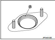
CAUTION:
• Place the reservoir tank with the chamfered pin hole (
)
facing up.
• Always set copper plates or cloth between vise grips when fixing the cylinder body to a vise.
• Never overtighten the vise.
4. Tilt the reservoir tank so that a mounting pin can be inserted. Insert a mounting pin. Return the reservoir tank to the horizontal position. Insert another mounting pin into the pin hole on the opposite side in the same manner after the mounting pin passes through the cylinder body pin hole.
CAUTION:
Never reuse the mounting pin.
Inspection
INSPECTION BEFORE REMOVAL
Check the brake fluid level switch.
• Without ESP: Refer to BRC-73, "Component Inspection".
• With ESP: Refer to BRC-194, "Component Inspection".
INSPECTION AFTER INSTALLATION
Check the following items and replace if necessary.
• Check the master cylinder for deformation, twist, contact with other parts or looseness of connection.
• Check for fluid leakage from connection. Refer to BR-97, "FRONT : Inspection".
CAUTION:
If the fluid leakage is present, retighten to the specified torque. Replace if
necessary.
 Brake piping
Front : Exploded View
WITHOUT ESP
1. Brake booster
2. Master cylinder assembly
3. Brake tube
4. Connector bracket
5. Connector
6. ABS actuator and electric unit (control
unit)
7. Lock p ...
 Brake booster
Exploded View
2WD
MR16DDT, HR16DE
1. Master cylinder assembly
2. Vacuum pipe
3. Brake booster
4. Lock nut
5. Clevis
6. Gasket
: N·m (kg-m, ft-lb)
K9K
1. Master cylinder assembly
2 ...
Other materials:
System
System Diagram
System Description
REFRIGERANT CYCLE
Refrigerant Flow
The refrigerant from the compressor, flows the condenser with liquid tank, the
evaporator, and returns to the
compressor. The refrigerant evaporation in the evaporator is controlled by an
expansion valve.
Freeze Prote ...
P0500 VSS
Description
The vehicle speed signal is sent to the combination meter from the “ABS
actuator and electric unit (control
unit)” by CAN communication line. The combination meter then sends a signal to
the ECM by CAN communication
line.
DTC Logic
DTC DETECTION LOGIC
NOTE:
• If DTC P0500 is d ...
System
EPS system : System Description
• EPS control unit performs an arithmetical operation on data, such
as steering wheel turning force (sensor signal) from the torque
sensor, vehicle speed signal, etc. Then it generates an optimum
assist torque signal to the EPS motor according to the driving condi ...
