Nissan Juke Service and Repair Manual : Brake booster
Exploded View
2WD
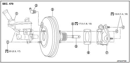
1. Master cylinder assembly
2. Vacuum pipe
3. Brake booster
4. Lock nut
5. Clevis
6. Gasket
7. Spacer
 : N·m (kg-m, ft-lb)
4WD
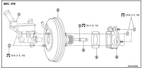
1. Master cylinder assembly
2. Brake booster
3. Lock nut
4. Clevis
5. Gasket
6. Spacer
 : N·m (kg-m, ft-lb)
Removal and installation
REMOVAL
1. Perform inspection before removal. Refer to BR-47, "Inspection and Adjustment".
2. Remove cowl top and cowl top extension. Refer to EXT-20, "Removal and Installation".
3. Remove air duct and air cleaner case.
• MR16DDT: Refer to EM-26, "Removal and Installation".
• HR16DE: Refer to EM-161, "Removal and Installation".
• K9K: Refer to EM-280, "Removal and Installation".
4. Remove brake master cylinder assembly. Refer to BR-42, "Removal and Installation".
5. Remove vacuum hose from brake booster.
• MR16DDT: Refer to BR-49, "MR16DDT : Removal and Installation".
• HR16DE: Refer to BR-50, "HR16DE : Removal and Installation".
• K9K: Refer to BR-52, "K9K : Removal and Installation".
6. Remove snap pin (1) and clevis pin (2). Refer to BR-20, "Exploded View".
7. Remove nuts on brake booster and brake pedal assembly.
CAUTION:
Hold the brake booster so as to avoid dropping out.
8. Remove brake booster and spacer.
CAUTION:
Never deform or bend the brake tubes.
NOT
E:
If removing brake booster is difficult, remove clevis from brake
booster.
9. Remove vacuum pipe from brake booster. (2WD) 10. Remove spacer from brake booster.
11. Perform inspection after removal. Refer to BR-47, "Inspection and Adjustment".
INSTALLATION
CAUTION:
Never spill or splash brake fluid on painted surfaces. Brake fluid may seriously
damage paint. Wipe it
off immediately and wash with water if it gets on a painted surface.
Note the following, and install in the reverse order of removal.
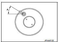
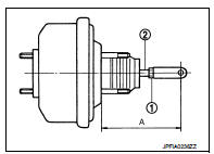
• Set vacuum pipe angle (A) as shown in the figure. (2WD)
A : 50 – 60°
• Be careful not to damage brake booster stud bolt threads. If brake booster is tilted during installation, the dash panel may damage the threads.
• Never deform or bend the brake tubes when installing the brake booster.
• Always use a gasket between the brake booster and the spacer.
• Replace the clevis pin if it is damaged. Refer to BR-22, "Inspection and Adjustment".
• Perform the air bleeding. Refer to BR-13, "Bleeding Brake System".
• Check each item of brake pedal. Adjust it if the measurement value is not the standard. Refer to BR-9, "Inspection and Adjustment".
Inspection and Adjustmen
INSPECTION BEFORE REMOVAL
Air Tight
CAUTION:
Check the air tight condition when the master cylinder and the brake booster is
installed.
1. Check the air tight use a handy vacuum pump.
At vacuum of −66.7 kPa (−500 mmHg, −19.69 inHg, −0.067 bar) : Vacuum should decrease within 3.3 kPa (24.8 mmHg, 0.98 inHg, 0.033 bar) for 15 seconds.
2. If the air tight condition cannot be maintained, perform the following operation.
a. Check the no dirt and dust are present on the brake booster and brake master cylinder mating faces.
Clean it if necessary.
b. Check the O-ring on the master cylinder. If anything is found, replace the O-ring. Refer to BR-42, "Removal and Installation".
c. Check the air tight condition again. If the condition still cannot be maintained, replace the brake booster.
INSPECTION AFTER REMOVAL
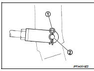
Input Rod Length Inspection 1. Loosen the lock nut (1) and adjust the input rod (2) to the specified length (A).
A : Refer to BR-70, "Brake Booster".
2. Tighten the lock nut to the specified torque.
INSPECTION AFTER INSTALLATION
Operation
Depress the brake pedal several times at 5-second intervals with the engine
stopped. Start the engine with the
brake pedal fully depressed. Check that the clearance between brake pedal and
dash lower panel decreases.
NOTE
:
A slight impact with a small click may be felt on the pedal when the brake pedal
is fully depressed. This is a
normal phenomenon due to the brake system operation.
Air Tight
1. Run the engine at idle for 1 minute to apply vacuum to the brake booster, and
stop the engine.
2. Depress the brake pedal several times at 5-second intervals until the accumulated vacuum is released to atmospheric pressure. Check that the clearance between brake pedal and dash lower panel gradually increases each time the brake pedal is depressed when performing this operation.
3. Depress the brake pedal with the engine running. Then stop the engine while holding down the brake pedal. Check that the brake pedal stroke does not change after holding down the brake pedal for 30 seconds or more.
ADJUSTMENT AFTER INSTALLATION
Perform the brake pedal adjustment after installing the brake pedal assembly. Refer to BR-9, "Inspection and Adjustment".
 Brake master cyl
Exploded View
2WD
1. Reservoir cap
2. Oil strainer
3. Reservoir tank
4. Cylinder body
5. Pin
6. O-ring
7. Grommet
: Apply polyglycol ether based
lubricant.
: Apply brake fluid.
: N· ...
 Vacuum lines
MR16DDT : Exploded View
1. Clamp
2. Vacuum hose A
3. Vacuum piping
4. Vacuum hose B
A. To engine side
B. Paint mark C. To brake booster
MR16DDT : Removal and Installation
REMOVAL
1. Remo ...
Other materials:
For side and rollover collision : When SRS is activated in a collision
CAUTION:
Due to varying models and option levels, not all parts listed in the chart below
apply to all vehicles.
WORK PROCEDURE
1. Before performing any of the following steps, ensure that all vehicle body
and structural repairs have been
completed.
2. Replace the following components:
• ...
Turbocharger
Exploded View
1. Heat insulator
2. Actuator hose
3. Clamp
4. Turbocharger inlet tube
5. Gasket
6. Gasket
7. Clamp
8. Oil outlet hose
9. Oil return pipe
10. Oil supply tube
11. O-ring
12. O-ring
13. Turbocharger
14. Eye bolt
15. Gasket
16. Oil supply tube
A. To EVAP canis ...
Map light control switch (if so equipped)
The map lights control switch has three positions: ON1 , OFF2 and center.
ON position
When the switch is in the ON position 1 , the map lights will illuminate.
OFF position
When the switch is in the OFF position2 , the map lights will not illuminate,
regardless of the condition.
Center posi ...
