Nissan Juke Service and Repair Manual : Both side headlamps (LO) are not turned on
Description
Both side headlamps (LO) are not turned ON in any condition.
Diagnosis Procedure
1.CHECK COMBINATION SWITCH
Check the combination switch. Refer to BCS-92, "Symptom Table".
Is the inspection result normal? YES >> GO TO 2.
NO >> Repair or replace the malfunctioning part.
2.CHECK HEADLAMP (LO) REQUEST SIGNAL INPUT
 CONSULT-III DATA MONITOR
1. Select “HL LO REQ” of IPDM E/R data monitor item.
2. With operating the lighting switch, check the monitor status.
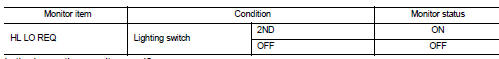
Is the inspection result normal? YES >> GO TO 3.
NO >> Replace BCM. Refer to BCS-93, "Removal and Installation" (with Intelligent Key), BCS-161, "Removal and Installation" (without Intelligent Key).
3.HEADLAMP (LO) CIRCUIT INSPECTION
Check the headlamp (LO) circuit. Refer to EXL-47, "Component Function Check".
Is the inspection result normal? YES >> Replace IPDM E/R.
NO >> Repair or replace the malfunctioning part.
 Both side headlamps (HI) are not turned on
Description
Both side headlamps (HI) are not turned ON when setting to the lighting
switch HI or PASS.
Diagnosis Procedure
1.COMBINATION SWITCH INSPECTION
Check the combination switch. Refer to ...
 Parking, license plate and tail lamps are not turned on
Without daytime running light system
WITHOUT DAYTIME RUNNING LIGHT SYSTEM : Description
The parking, license plate, tail lamps and each illumination are not turned
ON in any condition.
WITHOUT DA ...
Other materials:
Contents
• A QUICK REFERENCE INDEX, a black tab (e.g.
) is provided on the first page. You can quickly find the
first page of each section by matching it to the section's black tab.
• THE CONTENTS are listed on the first page of each section.
• THE TITLE is indicated on the upper portion of each pag ...
Thermo control amplifier
Removal and Installation
REMOVAL
1. Remove evaporator. Refer to HA-115, "EVAPORATOR : Removal and
Installation".
2. Remove thermo control amp. from evaporator.
INSTALLATION
Note the following items, and then install in the reverse order of removal.
CAUTION:
• Replace O-ring wi ...
Rear window defogger system
Wiring Diagram - DEFOGGER CONTROL SYSTEM -
For connector terminal arrangements, harness layouts, and alphabets in a
(option abbreviation; if not
described in wiring diagram), refer to GI-12, "Connector Information/Explanation
of Option Abbreviation".
...
