Nissan Juke Service and Repair Manual : Blower motor
Diagnosis Procedure
1.CHECK SYMPTOM
Check symptom (A, B or C).
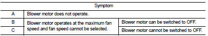
Which symptom is detected? A >>GO TO 2.
B >>GO TO 11.
C >> GO TO 13.
2.CHECK FUSE
1. Turn ignition switch OFF.
2. Check following fuses.
- 10A fuse [No. 15, located in fuse block (J/B)] - 15A fuses [Nos. 14 and 16, located in the fuse block (J/B)]
NOTE
:
Refer to PG-22, "Fuse, Connector and Terminal Arrangement".
Is the inspection result normal? YES >> GO TO 3.
NO >> Replace the blown fuse after repairing the affected circuit if a fuse is blown.
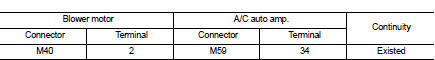
3.CHECK BLOWER MOTOR POWER SUPPLY
1. Disconnect blower motor connector.
2. Turn ignition switch ON.
3. Check voltage between blower motor harness connector and ground.
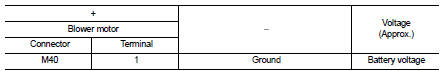
Is the inspection result normal? YES >> GO TO 5.
NO >> GO TO 4.
4.CHECK BLOWER RELAY
1. Turn ignition switch OFF.
2. Check blower relay. Refer to HAC-173, "Component Inspection (Blower Relay)".
Is the inspection result normal? YES >> Repair harness or connector between blower motor and fuse.
NO >> Replace blower relay.
5.CHECK FAN CONTROL AMP. POWER SUPPLY (SOURCE) CIRCUIT
1. Turn ignition switch OFF.
2. Connect blower motor connector.
3. Disconnect fan control amp. connector.
4. Turn ignition switch ON.
5. Check voltage between fan control amp. harness connector and ground.
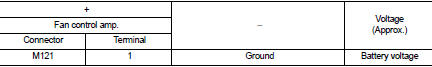
Is the inspection result normal? YES >> GO TO 7.
NO >> GO TO 6.
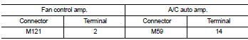
6.CHECK FAN CONTROL AMP. POWER SUPPLY (SOURCE) CIRCUIT FOR OPEN
1. Turn ignition switch OFF.
2. Disconnect blower motor connector.
3. Check continuity between fan control amp. harness connector and blower motor harness connector.
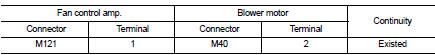
Is the inspection result normal? YES >> Replace blower motor. Refer to VTL-15, "Removal and Installation (LHD models)" or VTL-16, "Removal and Installation (RHD models)".
NO >> Repair harness or connector.
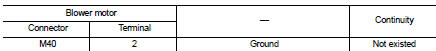
7.CHECK FAN CONTROL AMP. GROUND (DRAIN) CIRCUIT FOR OPEN
1. Turn ignition switch OFF.
2. Check continuity between fan control amp. harness connector and ground.
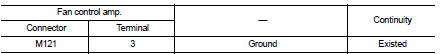
Is the inspection result normal? YES >> GO TO 8.
NO >> Repair harness or connector.
8.CHECK FAN CONTROL AMP. CONTROL SIGNAL (GATE) CIRCUIT FOR OPEN
1. Disconnect A/C auto amp. connector.
2. Check continuity between fan control amp. harness connector and A/C auto amp. harness connector.
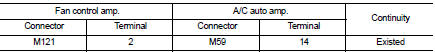
Is the inspection result normal? YES >> GO TO 9.
NO >> Repair harness or connector.
9.CHECK FAN CONTROL AMP. CONTROL SIGNAL (GATE) CIRCUIT FOR SHORT
Check continuity between fan control amp. harness connector and ground.
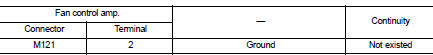
Is the inspection result normal? YES >> GO TO 10.
NO >> Repair harness or connector.
10.CHECK FAN CONTROL AMP.
Check fan control amp. Refer to HAC-173, "Component Inspection (Fan Control Amp.)".
Is the inspection result normal? YES >> Replace A/C auto amp. Refer to HAC-188, "Removal and Installation".
NO >> Replace fan control amp. Refer to HAC-194, "Removal and Installation".
11.CHECK A/C AUTO AMP. IGNITION POWER SUPPLY FEEDBACK SIGNAL
1. Turn ignition switch ON.
2. Check voltage between A/C auto amp. harness connector and ground.
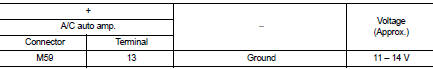
Is the inspection result normal? YES >> GO TO 12.
NO >> Repair harness or connector between A/C auto amp. and fuse.
12.CHECK BLOWER MOTOR FEEDBACK SIGNAL CIRCUIT FOR OPEN
1. Turn ignition switch OFF.
2. Disconnect blower motor connector and A/C auto amp. connector.
3. Check continuity between blower motor harness connector and A/C auto amp. harness connector.
Is the inspection result normal? YES >> Replace A/C auto amp. Refer to HAC-188, "Removal and Installation".
NO >> Repair harness or connector.
13.CHECK BLOWER MOTOR FEEDBACK SIGNAL CIRCUIT AND FAN CONTROL AMP. POWER SUPPLY (SOURCE) CIRCUIT FOR SHORT
1. Turn ignition switch OFF.
2. Disconnect following connectors.
- Blower fan motor
- Fan control amp.
- A/C auto amp.
3. Check continuity between blower motor harness connector and ground.
Is the inspection result normal? YES >> GO TO 14.
NO >> Repair harness or connector.
14.CHECK FAN CONTROL AMP. CONTROL SIGNAL (GATE) CIRCUIT FOR SHORT TO POWER SUPPLY
Check harness between fan control amp. harness connector and A/C auto amp. harness connector for short to power supply.
Is the inspection result normal? YES >> GO TO 10.
NO >> Repair harness or connector.
Component Inspection (Blower Motor)
1.CHECK BLOWER MOTOR
1. Remove blower motor. Refer to VTL-15, "Removal and Installation (LHD models)" or VTL-16, "Removal and Installation (RHD models)".
2. Check that there is not any mixing foreign object in the blower motor.
Is the inspection result normal? YES >> GO TO 2.
NO >> Replace blower motor. Refer to VTL-15, "Removal and Installation (LHD models)" or VTL-16, "Removal and Installation (RHD models)".
2.CHECK BLOWER MOTOR
Check that there is not breakage or damage in the blower motor.
Is the inspection result normal? YES >> GO TO 3.
NO >> Replace blower motor. Refer to VTL-15, "Removal and Installation (LHD models)" or VTL-16, "Removal and Installation (RHD models)".
3.CHECK BLOWER MOTOR
Check that blower motor turns smoothly.
Is the inspection result normal? YES >> INSPECTION END
NO >> Replace blower motor. Refer to VTL-15, "Removal and Installation (LHD models)" or VTL-16, "Removal and Installation (RHD models)".
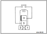
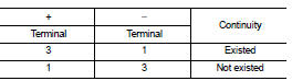
Component Inspection (Blower Relay)
1.CHECK BLOWER RELAY
1. Remove blower relay. Refer to PG-22, "Fuse, Connector and Terminal Arrangement".
2. Check continuity between blower relay terminal 3 and 5 when the voltage is supplied between terminal 1 and 2.
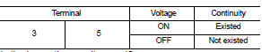
Is the inspection result normal? YES >> INSPECTION END
NO >> Replace blower relay.
Component Inspection (Fan Control Amp.)
1.CHECK FAN CONTROL AMP.
1. Remove fan control amp. Refer to HAC-194, "Removal and Installation".
2. Check continuity between fan control amp. terminals.
Is the inspection result normal? YES >> INSPECTION END
NO >> Replace fan control amp. Refer to HAC-194, "Removal and Installation".
 Blower fan on signal
Component Function Check
1.CHECK BLOWER FAN ON SIGNAL
With CONSULT-III
1. Turn ignition switch ON.
2. Select “AIR CONDITIONER” of “BCM” using CONSULT-III.
3. Select “FAN ON SIG” in “DATA MONITOR” ...
 Magnet clutch
Component Function Check
1.CHECK MAGNET CLUTCH OPERATION
Perform auto active test of IPDM E/R. Refer to PCS-12, "Diagnosis
Description" (with Intelligent Key) or PCS-
43, "Diagnosi ...
Other materials:
B260C steering lock unit
DTC Logic
DTC DETECTION LOGIC
DTC CONFIRMATION PROCEDURE
1.PERFORM DTC CONFIRMATION PROCEDURE
1. Shift selector lever to the P position.
2. Press push-button ignition switch under the following condition.
- Brake pedal: Not depressed
3. Turn ignition switch ON.
4. Turn ignition switch OFF. ...
No engine braking
Description
CHART 11: NO ENGINE BRAKING
Diagnosis Procedure
1.CHECK ECM POWER SUPPLY AND GROUND CIRCUIT
Check ECM power supply and ground circuit. Refer to EC-885, "Diagnosis
Procedure".
Is the inspection result normal?
YES >> GO TO 2.
NO >> Repair or replace harne ...
Intelligent key battery
Removal and Installation
1. Release the lock knob at the back of the Intelligent Key and remove the
mechanical key.
2. Insert a flat-blade screwdriver (A) wrapped with a cloth into the
slit of the corner and twist it to separate the upper part from the
lower part.
CAUTION:
• Do not touch t ...
