Nissan Juke Service and Repair Manual : BCM branch line circuit
Diagnosis Procedure
1.CHECK CONNECTOR
1. Turn the ignition switch OFF.
2. Disconnect the battery cable from the negative terminal.
3. Check the terminals and connectors of the BCM for damage, bend and loose connection (unit side and connector side).
Is the inspection result normal? YES >> GO TO 2.
NO >> Repair the terminal and connector.
2.CHECK HARNESS FOR OPEN CIRCUIT
1. Disconnect the connector of BCM.
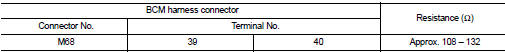
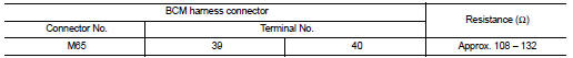
2. Check the resistance between the BCM harness connector terminals.
- Models with Intelligent Key system
- Models without Intelligent Key system
Is the measurement value within the specification? YES >> GO TO 3.
NO >> Repair the BCM branch line.
3.CHECK POWER SUPPLY AND GROUND CIRCUIT
Check the power supply and the ground circuit of the BCM. Refer to the following.
• Models with Intelligent Key system: BCS-87, "Diagnosis Procedure" • Models without Intelligent Key system: BCS-155, "Diagnosis Procedure"
Is the inspection result normal? YES (Present error)>>Replace the BCM. Refer to the following.
• Models with Intelligent Key system: BCS-93, "Removal and Installation" • Models without Intelligent Key system: BCS-161, "Removal and Installation"
YES (Past error)>>Error was detected in the BCM branch line.
NO >> Repair the power supply and the ground circuit.
 PTC branch line circuit
Diagnosis Procedure
1.CHECK CONNECTOR
1. Turn the ignition switch OFF.
2. Disconnect the battery cable from the negative terminal.
3. Check the terminals and connectors of the PTC heater control u ...
 Can communication circuit
Diagnosis Procedure
1.CONNECTOR INSPECTION
1. Turn the ignition switch OFF.
2. Disconnect the battery cable from the negative terminal.
3. Disconnect all the unit connectors on CAN communication s ...
Other materials:
Control cable
Exploded View
1. Control cable
2. Lock plate
3. Transaxle assembly
4. Bracket A
5. Bracket B
6. CVT shift selector assembly
A: Manual lever
B: Grommet
: N·m (kg-m, ft-lb)
: N·m (kg-m, in-lb)
Removal and Installation
INSTALLATION
CAUTION:
Always apply the parking brake before per ...
Headlining
Exploded View
LHD models
1. Headlining assembly
2. Assist grip clip
3. Rear assist grip RH
4. Front assist grip RH
5. Sun visor assembly RH
6. Sun visor cover RH
7. Sun visor cover LH
8. Sun visor assembly LH
9. Rear assist grip LH
10. Headlining clip
11. Sun visor holder RH
1 ...
Exploded View
1. Main muffler
2. Mounting rubber
3. Ring gasket
4. Center tube
5. Exhaust gas temperature sensor 2
6. Diesel particulate filter assembly
7. Gasket
8. Stud bolt
9. Diesel particulate filter inlet tube
10. Gasket
A. To exhaust manifold
B. To pressure hose
: N·m (kg-m, ft-lb)
: ...
