Nissan Juke Service and Repair Manual : BCM
LHD
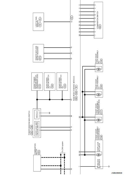
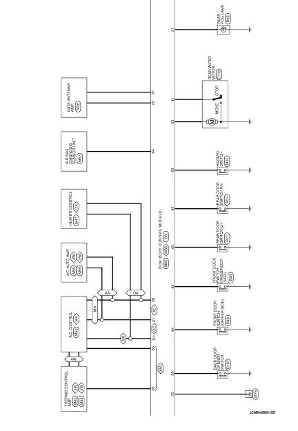
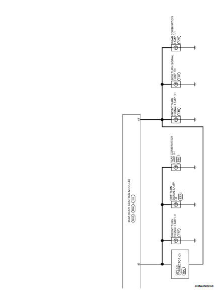
LHD : Wiring Diagram
For connector terminal arrangements, harness layouts, and alphabets in a
 (option abbreviation; if not
described in wiring diagram), refer to GI-12, "Connector Information/Explanation
of Option Abbreviation".

 Wiring diagram
...
 RHD
RHD
RHD : Wiring Diagram
For connector terminal arrangements, harness layouts, and alphabets in a
(option abbreviation; if not
described in wiring diagram), refer to GI-12, "Connector Information ...
Other materials:
System
METER SYSTEM
METER SYSTEM : System Diagram
*: K9K engine models
METER SYSTEM : System Description
COMBINATION METER
• The combination meter receives necessary signals from each unit, switch,
and sensor to control the following
functions.
- Measuring instruments
- Shift position indicat ...
C1101, C1102, C1103, C1104 wheel sensor
DTC Logic
DTC DETECTION LOGIC
DTC CONFIRMATION PROCEDURE
1.PRECONDITIONING
If “DTC CONFIRMATION PROCEDURE” has been previously conducted, always turn
ignition switch OFF and
wait at least 10 seconds before conducting the next test.
>> GO TO 2.
2.CHECK DTC DETECTION
With CONSULT ...
P0715 input speed sensor A
DTC Logic
DTC DETECTION LOGIC
DTC CONFIRMATION PROCEDURE
CAUTION:
Be careful of the driving speed.
1.PREPARATION BEFORE WORK
If another "DTC CONFIRMATION PROCEDURE" occurs just before, turn ignition
switch OFF and wait for at
least 10 seconds, then perform the next test.
> ...
