Nissan Juke Service and Repair Manual : Basic inspection
Description
NOTE
:
Only consult the tests after following the diagnostic procedure chart.
Some specific checks are grouped under the ???tests??? heading and are used as required in different diagnostic charts.
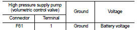
Work Procedure (TEST 1: Low Pressure Fuel Supply System Check)
NOTE
:
• CAUSE
- No fuel can be seen in the transparent supply pipe leading to the pump or large air bubbles can be seen (small air bubbles are permitted).
- engine does not start.
1.CHECK CONFORMITY
Check the conformity and presence of the fuel (gasoline instead of diesel, contaminated fuel).
Is the inspection result normal? Yes >> GO TO 2.
No >> Bleed the fuel supply system with the manual priming pump.
2.CHECK FUEL CIRCUIT
Does the fuel circulate correctly when pumped manually? Yes or No Yes >> GO TO 5.
No >> GO TO 3.
3.CHECK FOR LEAK
Look for leaks on the unions.
Are there leaks in the hoses and unions? Yes >> Carry out the required repairs.
No >> GO TO 4.
4.CHECK FUEL FILTER
Check the correctness of the fuel filter.
Is the fuel filter correct? Yes >> GO TO 5.
No >> Replace the fuel filter with a genuine part.
5.INSPECTION END
Low pressure circuit OK.
>> INSPECTION END
Work Procedure (TEST 2: Internal Fuel Transfer Pump Check)
NOTE
:
• CONDITIONS PRIOR TO TEST
- Test 1 Low pressure fuel supply system check has been carried out previously and results are satisfactory.
• CAUSE
- Fuel can be seen in the transparent supply pipe leading to the pump.
- However, fuel does not move during starting.
1.CHECK INTERNAL FUEL TRANSFER PUMP
1. Disconnect high pressure supply pump (volumetric control valve) harness connector.
2. Remove fuel return pipe from the pump and block it so that it is sealed. Connect a pipe to the pump to measure the flow of diesel.
3. To authorise a 15 second cranking engine and carry out this test it is essential to carry out the following procedure: measure the flow of diesel.
- Turn ignition switch ON.
- Perform ???SAVE DATA FOR CPU REPLC??? in WORK SUPPORT mode with CONSULT-III.
- Perform ???PRGRM REINITIALIZE??? in WORK SUPPORT mode with CONSULT-III.
- Cranking engine for at least 15 seconds (starting speed 250 rpm).
- Check the flow rate of the fuel being collected in a graduated measuring cylinder (500 ml minimum).The minimum flow rate must be 25 ml every 15 sec.
- Perform ???WRT DATA AFTR REPLC CPU??? in WORK SUPPORT mode with CONSULT-III.
Does the flow measure less than 25ml? Yes >> Replace high pressure supply pump.
No >> GO TO 2.
2.INSPECTION END
Low pressure system OK.
>> INSPECTION END
Work Procedure [TEST 3: High Pressure Supply Pump (Pressure Control Valve) Check]
NOTE
:
• CONDITIONS PRIOR TO TEST
- The entire low pressure system must be in good condition.
- Check the sealing of the high pressure pipes and unions.
• CAUSE
- Rail pressure approximately 5000 kPa (50 bar, 51 kg/cm2, 725 psi) during starting.
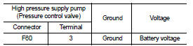
1.CHECK HIGH PRESSURE SUPPLY PUMP (PRESSURE CONTROL VALVE) POWER SUPPLY
1. Turn ignition switch OFF.
2. Disconnect high pressure supply pump (pressure control valve) harness connector.
3. Turn ignition switch ON.
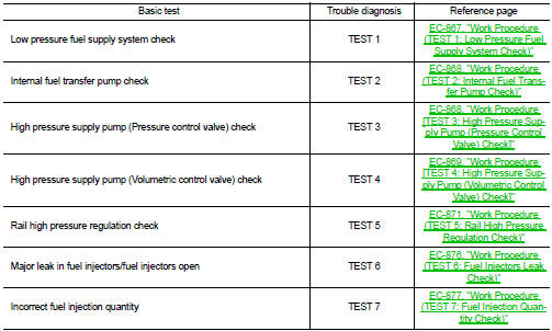
4. Check the voltage between high pressure supply pump (pressure control valve) harness connector and ground.
Is the inspection result normal? YES >> GO TO 3.
NO >> GO TO 2.
2.DETECT MALFUNCTIONING PART
Check the following.
• IPDM E/R
• Harness for open or short between IPDM E/R and high pressure supply pump
(pressure control valve)
• Harness for open or short between ECM and high pressure supply pump (pressure
control valve)
>> Repair open circuit or short to ground or short to power in harness or connectors.
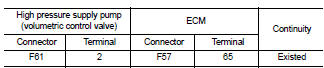
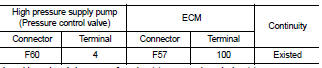
3.CHECK HIGH PRESSURE SUPPLY PUMP (PRESSURE CONTROL VALVE) OUTPUT SIGNAL CIRCUIT FOR OPEN AND SHORT
1. Turn ignition switch OFF.
2. Disconnect ECM harness connector.
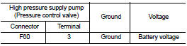
3. Check the continuity between high pressure supply pump (pressure control valve) harness connector and ECM harness connector.
4. Also check harness for short to ground and short to power.
Is the inspection result normal? YES >> GO TO 4.
NO >> Repair open circuit or short to ground or short to power in harness or connectors.
4.HIGH PRESSURE SUPPLY PUMP (PRESSURE CONTROL VALVE) CHECK
Refer to EC-900, "Component Inspection".
Is the inspection result normal? Yes >> INSPECTION END
No >> Replace high pressure supply pump.
Work Procedure [TEST 4: High Pressure Supply Pump (Volumetric Control Valve) Check]
NOTE
:
• CONDITIONS PRIOR TO TEST
- The entire low pressure system must be in good condition.
- Check the sealing of the high pressure pipes and unions.
• CAUSE
- Not enough or no rail pressure during starting.
- Rail reference pressure during starting, minimum 15,000 kPa (150 bar, 153 kg/cm2, 2,175 psi).
1.CHECK HIGH PRESSURE SUPPLY PUMP (VOLUMETRIC CONTROL VALVE)-I
Refer to EC-889, "Component Inspection".
Is the inspection result normal? YES >> GO TO 2
NO >> Replace high pressure supply pump.
2.CHECK HIGH PRESSURE SUPPLY PUMP (VOLUMETRIC CONTROL VALVE)-II
• Reconnect all harness connectors disconnected.
• Turn ignition switch ON.
• Select ???DATA MONITOR??? mode with CONSULT-III.
• Check that the ???FUEL FLOW S/V CU??? indication when the cranking engine.
Is the excitation current between 0.6 - 1.0A? YES >> GO TO 6.
NO >> GO TO 3.
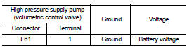
3.CHECK HIGH PRESSURE SUPPLY PUMP (VOLUMETRIC CONTROL VALVE) POWER SUPPLY
1. Turn ignition switch OFF.
2. Disconnect high pressure supply pump (volumetric control valve) harness connector.
3. Turn ignition switch ON.
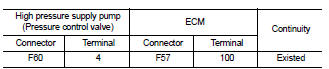
4. Check the voltage between high pressure supply pump (volumetric control valve) harness connector and ground.
Is the inspection result normal? YES >> GO TO 5.
NO >> GO TO 4.
4.DETECT MALFUNCTIONING PART
Check the following.
• IPDM E/R
• Harness for open or short between ECM and high pressure supply pump
(volumetric control valve)
• Harness for open or short between IPDM E/R and high pressure supply pump
(volumetric control valve)
>> Repair open circuit or short to ground or short to power in harness or connectors.
5.CHECK HIGH PRESSURE SUPPLY PUMP (VOLUMETRIC CONTROL VALVE) OUTPUT SIGNAL CIRCUIT FOR OPEN AND SHORT
1. Turn ignition switch OFF.
2. Disconnect ECM harness connector.
3. Check the continuity between high pressure supply pump (volumetric control valve) harness connector and ECM harness connector.
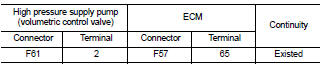
4. Also check harness for short to ground and short to power.
Is the inspection result normal? YES >> INSPECTION END
NO >> Repair open circuit or short to ground or short to power in harness or connectors.
6.CHECK ENGINE CONDITION
Start engine.
Is the engine start? YES >> GO TO 7.
NO >> GO TO 9.
7.CHECK ENGINE CONDITION
• Check that the oil level is correct and that the engine coolant temperature is normal operation temperature 60?°C (140?°F).
• Engine running at idle speed.
- Select ???HIGH PRES CIRCUIT LEAK TEST??? in ???ACTIVE TEST??? mode with CONSULT-III.
- Engine will perform 4 acceleration cycles.
- Select ???DATA MONITOR??? mode with CONSULT-III.
- Check that the ???RAIL PRES SET??? and ???RAIL PRESSURE??? indication.
- Does ???RAIL PRESSURER??? follow ???RAIL PRES SET??? at ?± 5,000 kPa (50 bar, 51 kg/cm2, 725 psi) during the phase of the 4 acceleration cycles? NOTE
:
If the rail pressure does not reach the set point there is an fuel injector leak
that is too great or the pressure
signal is incorrect.
Is the inspection result normal? YES >> GO TO 11.
NO >> GO TO 8.
8.CHECK RAIL HIGH PRESSURE CONTROL CIRCUIT
Carry out TEST 5.
>> GO TO 11.
9.CHECK ENGINE CONDITION
• Check that the oil level is correct.
• Select ???DATA MONITOR??? mode with CONSULT-III.
• Check that the ???RAIL PRES SET??? and ???RAIL PRESSURE??? indication.
• Does ???RAIL PRESSURER??? follow ???RAIL PRES SET??? when the cranking engine.
NOTE
:
If the rail pressure does not reach the set point there is an fuel injector leak
that is too great or the pressure
signal is incorrect.
Is the inspection result normal? YES >> GO TO 11.
NO >> GO TO 10.
10.CHECK MAJOR LEAK IN FUEL INJECTOR/FUEL INJECTORS OPEN Carry out TEST 6.
>> GO TO 11.
11.INSPECTION END
High pressure supply pump (volumetric control valve) OK.
>> INSPECTION END
Work Procedure (TEST 5: Rail High Pressure Regulation Check)
NOTE
:
• If contaminants (swarf) can be seen in the transparent return pipe, the entire
fuel injection system (fuel injectors,
pump, rail, high pressure pipes and all return pipes) must be replaced.
• CONDITIONS PRIOR TO TEST
- Engine coolant temperature between 80 - 90?°C (176 - 194?°F).
- All the electrical load are switched off.
- Air conditioning is switched off.
- The tank is at least half-full.
- The pipe connections and unions have been checked.
- Check the sealing of the high pressure pipes and unions.
• CAUSE
- Rail pressure variations around the set point.
- The rail reference pressure is not reached.
- Rough idle.
- Possibly noisy combustion.
1.CHECK AIR BUBBLES
1. Start engine
2. Are there large air bubbles in the transparent supply pipe going to the pump?
Is the inspection result normal?
YES >> Check low pressure system.
NO >> GO TO 2.
2.CHECK HIGH PRESSURE SUPPLY PUMP (VOLUMETRIC CONTROL VALVE)-I
Disconnect high pressure supply pump (volumetric control valve) harness connector.
Does the engine stop? YES >> GO TO 3.
NO >> Replace high pressure supply pump (the high pressure supply pump [volumetric control valve] remains open mechanically).
3.CHECK HIGH PRESSURE SUPPLY PUMP (PRESSURE CONTROL VALVE)-I
1. Reconnect high pressure supply pump (volumetric control valve) harness connector.
2. Turn ignition switch OFF and wait at least 30 seconds.
3. Start engine.
4. Disconnect high pressure supply pump (pressure control valve) harness connector.
Does the engine stop? YES >> GO TO 4.
NO >> Replace high pressure supply pump (the high pressure supply pump [pressure control valve] remains open mechanically).
4.CHECK FUEL INJECTOR
1. Reconnect high pressure supply pump (pressure control valve) harness connector.
2. Wait at least 30 seconds.
3. Start engine and let it idle speed.
4. Select ???DATA MONITOR??? mode with CONSULT-III.
5. Check that the ???F/FLOW CORR CYL1???, ???F/FLOW CORR CYL2???, ???F/FLOW CORR CYL3???, ???F/FLOW CORR CYL4??? indication.
Are the reference value 0.3 - 1.9? YES >> GO TO 6.
NO >> GO TO 5.
5.CHECK MAJOR LEAK IN FUEL INJECTOR/FUEL INJECTORS OPEN
Carry out TEST 6.
>> INSPECTION END
6.CHECK ENGINE CONDITION
• Check that the oil level is correct and that the engine coolant temperature is normal operation temperature.
60?°C (140?°F)
• Engine running at idle speed.
- Select ???HIGH PRES CIRCUIT LEAK TEST??? in ???ACTIVE TEST??? mode with CONSULT-III.
- Engine will perform 4 acceleration cycles.
- Select ???DATA MONITOR??? mode with CONSULT-III.
- Check that the ???RAIL PRES SET??? and ???RAIL PRESSURE??? indication.
- Does ???RAIL PRESSURE??? follow ???RAIL PRES SET??? at during the phase of 4 acceleration cycles? Is the inspection result normal? YES >> GO TO 22.
NO >> GO TO 7.
7.CHECK ENGINE COOLANT TEMPERATURE AND FUEL TEMPERATURE
1. Select ???DATA MONITOR??? mode with CONSULT-III.
2. Check that the ???FUEL TEMP??? indication when operating at idle speed is between 60 - 80?°C (140 - 176?°F) 3. Check that the ???WATER TEMP??? indication is between 80 - 90?°C (176 - 194?°F) NOTE
:
• When the fuel temperature is above 136?°C (277?°F), the maximum rail pressure is
reduced to protect the
plastic pipes.
• When the coolant temperature is above 100?°C (212?°F), the maximum rail pressure is reduced to protect the engine.
Are the ???FUEL TEMP??? and ???WATER TEMP??? within the reference value range? YES >> GO TO 8.
NO >> Check the fuel temperature sensor (Refer to EC-916, "Component Inspection") or engine coolant temperature sensor (Refer to EC-908, "Component Inspection").
8.CHECK HIGH PRESSURE SUPPLY PUMP (VOLUMETRIC CONTROL VALVE) POWER SUPPLY
1. Turn ignition switch OFF.
2. Disconnect high pressure supply pump (volumetric control valve) harness connector.
3. Turn ignition switch ON.
4. Check the voltage between high pressure supply pump (volumetric control valve) harness connector and ground.
Is the inspection result normal? YES >> GO TO 10.
NO >> GO TO 9.
9.DETECT MALFUNCTIONING PART
Check the following.
• IPDM E/R
• Harness for open or short between ECM and high pressure supply pump
(volumetric control valve)
• Harness for open or short between IPDM E/R and high pressure supply pump
(volumetric control valve)
>> Repair open circuit or short to ground or short to power in harness or connectors.
10.CHECK HIGH PRESSURE SUPPLY PUMP (VOLUMETRIC CONTROL VALVE) OUTPUT SIGNAL CIRCUIT FOR OPEN AND SHORT
1. Turn ignition switch OFF.
2. Disconnect ECM harness connector.
3. Check the continuity between high pressure supply pump (volumetric control valve) harness connector and ECM harness connector.
4. Also check harness for short to ground and short to power.
Is the inspection result normal? YES >> GO TO 11.
NO >> Repair open circuit or short to ground or short to power in harness or connectors.
11.CHECK HIGH PRESSURE SUPPLY PUMP (VOLUMETRIC CONTROL VALVE)-II
Refer to EC-889, "Component Inspection".
Is the inspection result normal? YES >> GO TO 12.
NO >> Replace high pressure supply pump.
12.CHECK HIGH PRESSURE SUPPLY PUMP (PRESSURE CONTROL VALVE) POWER SUPPLY
1. Turn ignition switch OFF.
2. Disconnect high pressure supply pump (pressure control valve) harness connector.
3. Turn ignition switch ON.
4. Check the voltage between high pressure supply pump (pressure control valve) harness connector and ground.
Is the inspection result normal? YES >> GO TO 14.
NO >> GO TO 13.
13.DETECT MALFUNCTIONING PART
Check the following.
• IPDM E/R
• Harness for open or short between IPDM E/R and high pressure supply pump
(pressure control valve)
• Harness for open or short between ECM and high pressure supply pump (pressure
control valve)
>> Repair open circuit or short to ground or short to power in harness or connectors.
14.CHECK HIGH PRESSURE SUPPLY PUMP (PRESSURE CONTROL VALVE) OUTPUT SIGNAL CIRCUIT FOR OPEN AND SHORT
1. Turn ignition switch OFF.
2. Disconnect ECM harness connector.
3. Check the continuity between high pressure supply pump (pressure control valve) harness connector and ECM harness connector.
4. Also check harness for short to ground and short to power.
Is the inspection result normal? YES >> GO TO 15.
NO >> Repair open circuit or short to ground or short to power in harness or connectors.
15.CHECK HIGH PRESSURE SUPPLY PUMP (PRESSURE CONTROL VALVE)-II
Refer to EC-900, "Component Inspection".
Is the inspection result normal? YES >> GO TO 16.
NO >> Replace high pressure supply pump.
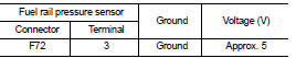
16.CHECK FUEL RAIL PRESSURE SENSOR POWER SUUPLY CIRCUIT
1. Turn ignition switch OFF.
2. Disconnect fuel rail pressure sensor harness connector.
3. Turn ignition switch ON.
4. Check the voltage between fuel rail pressure sensor harness connector and ground.
Is the inspection result normal? YES >> GO TO 17.
NO >> Repair open circuit or short to ground or short to power in harness or connectors.
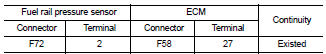
17.CHECK FUEL RAIL PRESSURE SENSOR GROUND CIRCUIT FOR OPEN AND SHORT
1. Turn ignition switch OFF.
2. Disconnect ECM harness connector.
3. Check the continuity between fuel rail pressure sensor harness connector and ECM harness connector.
4. Also check harness for short to ground and short to power.
Is the inspection result normal? YES >> GO TO 18.
NO >> Repair open circuit or short to ground or short to power in harness or connectors.
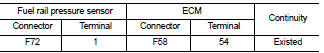
18.CHECK FUEL RAIL PRESSURE SENSOR INPUT SIGNAL CIRCUIT FOR OPEN AND SHORT
1. Check the continuity between fuel rail pressure sensor harness connector and ECM harness connector.
2. Also check harness for short to ground and short to power.
Is the inspection result normal? YES >> GO TO 19.
NO >> Repair open circuit or short to ground or short to power in harness or connectors.
19.CHECK FUEL RAIL PRESSURE SENSOR
Refer to EC-918, "Component Inspection".
Is the inspection result normal? YES >> GO TO 20.
NO >> Replace fuel rail.
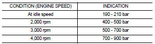
20.CHECK FUEL RAIL PRESSURE-I
1. Reconnect all harness connectors disconnected.
2. Start engine and let it idle speed.
3. Select ???DATA MONITOR??? mode with CONSULT-III.
4. Check that the ???RAIL PRESSURE??? indication under the following conditions.
NOTE
:
An unusual combustion noise may be heard.
Is the inspection result normal?
YES >> GO TO 22.
NO >> GO TO 21.
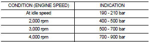
21.CHECK FUEL RAIL PRESSURE-II
1. Turn ignition switch OFF.
2. Replace fuel rail. Refer to EM-294, "Removal and Installation".
3. Start engine and let it idle speed.
4. Select ???DATA MONITOR??? mode with CONSULT-III.
5. Check that the ???RAIL PRESSURE??? indication under the following conditions.
NOTE
:
An unusual combustion noise may be heard.
Is the inspection result normal? YES >> GO TO 22.
NO >> Replace high pressure supply pump.
22.INSPECTION END
High pressure supply pump (volumetric control valve) OK.
>> INSPECTION END
Work Procedure (TEST 6: Fuel Injectors Leak Check)
NOTE
:
• CONDITIONS PRIOR TO TEST
- The entire low pressure system must be in good condition.
- Check the sealing of the high pressure pipes and unions.
- Test 3 High pressure supply pump (pressure control valve) check is OK - Test 4 High pressure supply pump (volumetric control valve) check is OK - Test 5 Rail high pressure regulation circuit check is OK.
• CAUSE
- Not enough or no rail pressure during starting.
- The engine does not start.
1.CHECK FUEL INJECTOR-I
Refer to EC-920, "Component Inspection".
Is the inspection result normal? YES >> GO TO 2.
NO >> Replace malfunctioning fuel injector.
2.CHECK INTERNAL FUEL TRANSFER PUMP
1. Turn ignition switch OFF.
2. Disconnect the return system connections at the fuel injectors and close off the return pipes so they are leak-tight.
3. To authorise a 15 second cranking engine and carry out this test it is essential to carry out the following procedure:
- Disconnect high pressure supply pump (volumetric control valve) harness
connector
- Turn ignition switch ON.
- Perform ???SAVE DATA FOR CPU REPLC??? in WORK SUPPORT mode with CONSULT-III.
- Perform ???PRGRM REINITIALIZE??? in WORK SUPPORT mode with CONSULT-III.
- Cranking engine for at least 15 seconds (starting speed 250 rpm) - Perform ???WRT DATA AFTR REPLC CPU??? in WORK SUPPORT mode with CONSULT-III.
Is the return volume at the fuel injectors more than 20 ml per fuel injector for the starting phase?
NOTE:
• Do not repeat this procedure more than 3 times and wait 30 seconds between
each 15 second cranking
engine.
• Then wait 30 minutes before cranking the engine for 315 second cycles.
• Follow this instruction so that the starter does not get damaged.
Does the flow measure more than 20 ml? Yes >> Replace malfunctioning fuel injector.
No >> GO TO 3.
3.CHECK FUEL INJECTOR-II
1. Turn ignition switch OFF.
2. Reconnect return pipes.
3. Start Engine.
4. Select ???DATA MONITOR??? mode with CONSULT-III.
5. Check ???RAIL PRESSURE??? and ???RAIL PRES SET??? indication.
6. Does ???RAIL PRESSURE??? follow ???RAIL PRES SET??? during the 3 second cranking engine? Is the inspection result normal? YES >> GO TO 5.
NO >> GO TO 4.
4.CHECK GLOW PLUG
1. Turn ignition switch OFF.
2. Remove the glow plugs and check for moisture.
3. If the glow plugs are wet with fuel, it is possible that the fuel injector is leaking.
Are the glow plugs wet with fuel? Yes >> Replace malfunction fuel injector.
No >> Replace high pressure supply pump.
5.INSPECTION END
Fuel injector system OK.
>> INSPECTION END
Work Procedure (TEST 7: Fuel Injection Quantity Check)
NOTE
:
• CONDITIONS PRIOR TO TEST
- The entire low pressure system must be in good condition.
- Check the sealing of the high pressure pipes and unions.
- Test 3 High pressure supply pump (pressure control valve) check is OK - Test 4 High pressure supply pump (volumetric control valve) check is OK - Test 5 Rail high pressure regulation circuit check is OK.
- All the electrical loads are switched off.
- Air conditioning is switched off.
• CAUSE
- The engine runs poorly at idle speed, possibly emits white smoke.
1.CHECK FUEL INJECTOR
Refer to EC-920, "Component Inspection".
Is the inspection result normal? YES >> GO TO 2.
NO >> Replace malfunctioning fuel injector.
2.CHECK ENGINE COOLANT TEMPERATURE AND FUEL TEMPERATURE
1. Start engine let it idle speed.
2. Select ???DATA MONITOR??? mode with CONSULT-III.
3. Check ???FUEL TEMP??? indication is above 60?°C (140?°F).
4. Check ???F/FLOW CORR CYL1???, ???F/FLOW CORR CYL2???, ???F/FLOW CORR CYL3???, ???F/FLOW CORR CYL4??? indication
Are the reference value 0.3 - 1.9? YES >> GO TO 3.
NO >> GO TO 4.
3.CHECK INTERNAL FUEL TRANSFER PUMP
1. Turn ignition switch OFF.
2. Disconnect the return system connections at the fuel injectors and close off the return pipes so they are leak-tight. While the engine is idling, check the return flow rate at the fuel injector. After 5 minutes the return volume must be between 16 - 24 ml per fuel injector.
Is there more than 24 ml or less than 16 ml of return for each fuel injector? Yes >> Replace malfunctioning fuel injector.
No >> INSPECTION END
4.CHECK COMPRESSION PRESSURE
Check compression pressure.
>> INSPECTION END
 Diagnosis and repair workflow
Work Flow
OVERALL SEQUENCE
• Malfunctions are declared as either present or stored (depending on whether
they appeared in a certain context
and have disappeared since, or whether they remain pr ...
 Additional service when replacing ECM
Description
When replacing ECM, this procedure must be performed.
Work Procedure
1.PRECONDITIONING
• Connect a CONSULT-III
• Connect a battery charger
• Electric load switch is OFF
• Wait for t ...
Other materials:
B1215, B1216, B1217 satellite sensor LH
DTC Logic
DTC DETECTION LOGIC
DTC CONFIRMATION PROCEDURE
1.CHECK SELF-DIAG RESULT
With CONSULT-III
1. Turn ignition switch ON.
2. Perform “Self Diagnostic Result” mode of “AIR BAG” using CONSULT-III.
Without CONSULT-III
1. Turn ignition switch ON.
2. Check the air bag warning lamp statu ...
P1610 lock mode
Description
ECM forcibly switches to the mode that inhibits engine start, when engine
start operation is performed 5 times
or more while communication between ECM and BCM is not normal.
DTC Logic
DTC DETECTION LOGIC
DTC CONFIRMATION PROCEDURE
1.PERFORM DTC CONFIRMATION PROCEDURE
1. Turn i ...
P1220 fuel pump control module
(FPCM)
DTC Logic
DTC DETECTION LOGIC
DTC CONFIRMATION PROCEDURE
1.PRECONDITIONING
1. Turn ignition switch OFF and wait at least 10 seconds.
2. Turn ignition switch ON.
3. Turn ignition switch OFF and wait at least 10 seconds.
TESTING CONDITION:
• Before performing the following procedure, confi ...
