Nissan Juke Service and Repair Manual : Back door opener system
System Diagram
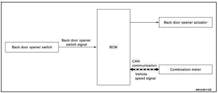
System Descr
BACK DOOR OPENER OPERATION
When back door opener switch is pressed, BCM operates back door opener actuator.
NOTE
:
Back door opener actuator is not for locking the back door. The function is only
to open the back door.
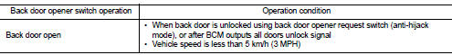
OPERATION CONDITION
If the following conditions are satisfied, back door opener operation is performed.
NOTE
:
• When battery terminal is disconnected and reconnected during all doors unlock
state, back door may not
open.
• Regardless of door lock actuator state, BCM resets recognition of all doors unlock state approximately 30 seconds after battery terminal is disconnected and BCM recognizes that all doors are in lock state.
• When battery terminal is reconnected and back door does not open, have BCM recognize that all doors are in unlock state.
 Remote keyless entry system
System Diagram
System Description
DOOR LOCK AND UNLOCK OPERATION
• When door lock and unlock button of keyfob is pressed, door lock and unlock
signal transmits from keyfob to
BCM via remote ke ...
 Diagnosis system (BCM)
Common item
COMMON ITEM : CONSULT-III Function (BCM - COMMON ITEM)
APPLICATION ITEM
CONSULT-III performs the following functions via CAN communication with BCM.
SYSTEM APPLICATION
BCM can perfo ...
Other materials:
Power supply routing circuit
Wiring Diagram - Battery power supply -
For connector terminal arrangements, harness layouts, and alphabets in a
(option abbreviation; if not
described in wiring diagram), refer to GI-12, "Connector Information/Explanation
of Option Abbreviation".
Wiring Diagram - Accessory p ...
Precaution Necessary for Steering Wheel Rotation after Battery Disconnect
NOTE:
• Before removing and installing any control units, first turn the ignition
switch to the LOCK position, then disconnect
both battery cables.
• After finishing work, confirm that all control unit connectors are connected
properly, then re-connect both
battery cables.
• Always use CONS ...
Wiring diagram
Engine control system
Wiring Diagram
For connector terminal arrangements, harness layouts, and alphabets in a
(option abbreviation; if not
described in wiring diagram), refer to GI-12, "Connector Information/Explanation
of Option Abbreviation".
...
