Nissan Juke Service and Repair Manual : B27A0, B27A1 intake door motor
DTC Logic
DTC DETECTION LOGIC
NOTE
:
• If DTC is displayed along with DTC U1000, first perform the trouble diagnosis
for DTC U1000. Refer to HAC-
51, "DTC Logic".
• If DTC is displayed along with DTC U1010, first perform the trouble diagnosis for DTC U1010. HAC-52, "DTC Logic".
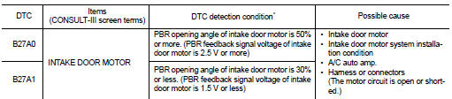
*: A/C auto amp. operates intake door motor according to target value of PBR opening angle at 40% when performing self-diagnosis.
DTC CONFIRMATION PROCEDURE
1.PERFORM DTC CONFIRMATION PROCEDURE
With CONSULT-III
1. Start engine.
2. Select “Self Diagnostic Result” mode of “HVAC” using CONSULT-III.
3. Check DTC.
Is DTC detected? YES >> Refer to HAC-65, "Diagnosis Procedure".
NO >> INSPECTION END
Diagnosis Procedure
1.CHECK INTAKE DOOR MOTOR OPERATION
1. Turn ignition switch ON.
2. Operate intake switch and check by operation sound that intake door motor operates.
Does the intake door motor operate? YES >> GO TO 2.
NO >> GO TO 8.
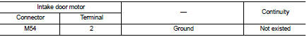
2.CHECK INTAKE DOOR MOTOR PBR POWER SUPPLY
1. Disconnect intake door motor connector.
2. Turn ignition switch ON.
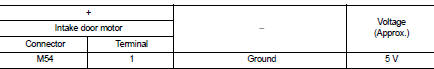
3. Check voltage between intake door motor harness connector and ground.
Is the inspection result normal? YES >> GO TO 3.
NO >> GO TO 7.
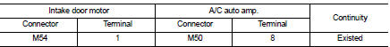
3.CHECK INTAKE DOOR MOTOR PBR GROUND CIRCUIT FOR OPEN
1. Turn ignition switch OFF.
2. Disconnect A/C auto amp. connector.
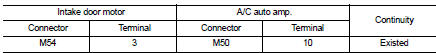
3. Check continuity between intake door motor harness connector and A/C auto amp. harness connector.
Is the inspection result normal? YES >> GO TO 4.
NO >> Repair harness or connector.
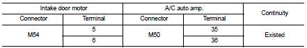
4.CHECK INTAKE DOOR MOTOR PBR FEEDBACK SIGNAL CIRCUIT FOR OPEN
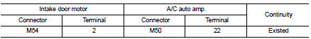
Check continuity between intake door motor harness connector and A/C auto amp. harness connector.
Is the inspection result normal? YES >> GO TO 5.
NO >> Repair harness or connector.
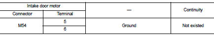
5.CHECK INTAKE DOOR MOTOR PBR FEEDBACK SIGNAL CIRCUIT FOR SHORT
Check continuity between intake door motor harness connector and ground.
Is the inspection result normal? YES >> GO TO 6.
NO >> Repair harness or connector.
6.CHECK INTAKE DOOR MOTOR PBR
Check intake door motor PBR. Refer to HAC-67, "Component Inspection (PBR)".
Is the inspection result normal? YES >> Replace A/C auto amp. Refer to HAC-91, "Removal and Installation".
NO >> Replace intake door motor. Refer to HAC-99, "INTAKE DOOR MOTOR : Removal and Installation".
7.CHECK INTAKE DOOR MOTOR PBR POWER SUPPLY CIRCUIT FOR OPEN
1. Turn ignition switch OFF.
2. Disconnect A/C auto amp. connector.
3. Check continuity between intake door motor harness connector and A/C auto amp. harness connector.
Is the inspection result normal? YES >> Replace A/C auto amp. Refer to HAC-91, "Removal and Installation".
NO >> Repair harness or connector.
8.CHECK INTAKE DOOR MOTOR DRIVE SIGNAL CIRCUIT FOR OPEN
1. Turn ignition switch OFF.
2. Disconnect intake door motor connector, and A/C auto amp. connector.
3. Check continuity between intake door motor harness connector and A/C auto amp. harness connector.
Is the inspection result normal? YES >> GO TO 9.
NO >> Repair harness or connector.
9.CHECK INTAKE DOOR MOTOR DRIVE SIGNAL CIRCUIT FOR SHORT
Check continuity between intake door motor harness connector and ground.
Is the inspection result normal? YES >> GO TO 10.
NO >> Repair harness or connector.
10.CHECK INTAKE DOOR MOTOR
1. Turn ignition switch OFF.
2. Check intake door motor. Refer to HAC-67, "Component Inspection (Motor)".
Is the inspection result normal? YES >> GO TO 11.
NO >> Replace intake door motor. Refer to HAC-99, "INTAKE DOOR MOTOR : Removal and Installation".
11.CHECK INSTALLATION OF INTAKE DOOR MOTOR SYSTEM
Check intake door motor system is properly installed. Refer to HAC-98, "Exploded View".
Is the inspection result normal? YES >> Replace A/C auto amp. Refer to HAC-91, "Removal and Installation".
NO >> Repair or replace malfunctioning parts.
Component Inspection (PBR)
1.CHECK INTAKE DOOR MOTOR PBR
Check resistance between intake door motor terminals.
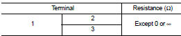
Is the inspection result normal? YES >> INSPECTION END
NO >> Replace intake door motor. Refer to HAC-99, "INTAKE DOOR MOTOR : Removal and Installation".
Component Inspection (Motor)
1.CHECK INTAKE DOOR MOTOR
Supply intake door motor terminals with battery voltage and check by visually and operation sound that intake door motor operates.
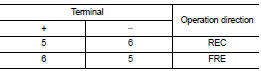
Is the inspection result normal? YES >> INSPECTION END
NO >> Replace intake door motor. Refer to HAC-99, "INTAKE DOOR MOTOR : Removal and Installation".
 B2630, B2631 sunload sensor
DTC Logic
DTC DETECTION LOGIC
NOTE:
• If DTC is displayed along with DTC U1000, first perform the trouble diagnosis
for DTC U1000. Refer to HAC-
51, "DTC Logic".
• If DTC is displayed ...
 B27A2, B27A3, B27A4, B27A5 air mix door motor
DTC Logic
DTC DETECTION LOGIC
NOTE:
• If DTC is displayed along with DTC U1000, first perform the trouble diagnosis
for DTC U1000. Refer to HAC-
51, "DTC Logic".
• If DTC is displayed ...
Other materials:
Heated seat switch
Exploded View
1. Heated seat swich
2. Switch bracket
3. Console switch finisher
Removal and Installation
REMOVAL
CAUTION:
When removing and installing, use shop cloths to protect from damage.
1. Remove the console switch finisher. Refer to IP-23, "Removal and
Installation".
...
Door lock actuator
Driver side
DRIVER SIDE : Component Function Check
1.CHECK FUNCTION
1. Select “DOOR LOCK” of “BCM” using CONSULT-III.
2. Select “DOOR LOCK” in “ACTIVE TEST” mode.
3. Check that the function operates normally according to the following
conditions.
Is the inspection result normal?
YES >& ...
Unit removal and installation
Transaxle assembly
Exploded View
1. CVT fluid level gauge
2. CVT fluid charging pipe
3. O-ring
4. Transaxle assembly
5. Air breather hose
A. For tightening torque, refer to TM-301, "Removal and Installation".
Removal and Intallation
REMOVAL
WARNING:
Never remove the reservo ...
