Nissan Juke Service and Repair Manual : B2627 outside antenna
DTC Logic
DTC DETECTION LOGIC
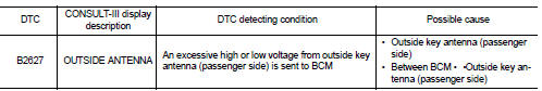
DTC CONFIRMATION PROCEDURE
1.PERFORM DTC CONFIRMATION PROCEDURE
1. Disconnect outside key antenna (passenger side) connector.
2. Perform “INTELLIGENT KEY” Self Diagnostic Result.
Is outside key antenna DTC detected? YES >> Refer to DLK-238, "Diagnosis Procedure".
NO >> Outside key antenna (passenger side) is OK.
Diagnosis Procedure
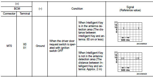
1.CHECK OUTSIDE KEY ANTENNA INPUT SIGNAL 1
1. Turn ignition switch OFF.
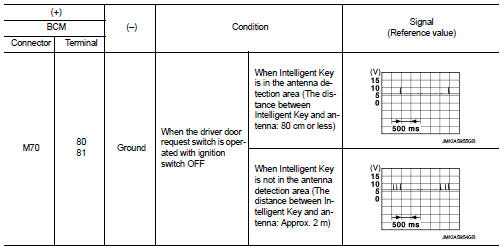
2. Check signal between BCM harness connector and ground using oscilloscope.
Is the inspection result normal? YES >> Replace BCM. Refer to BCS-93, "Removal and Installation".
NO >> GO TO 2.
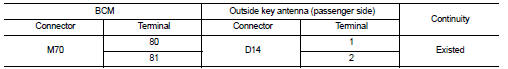
2.CHECK OUTSIDE KEY ANTENNA CIRCUIT
1. Disconnect BCM connector and outside key antenna (passenger side) connector.
2. Check continuity between BCM harness connector and outside key antenna (passenger side) harness connector.
3. Check continuity between BCM harness connector and ground.
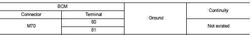
Is the inspection result normal? YES >> GO TO 3.
NO >> Repair or replace harness.
3.CHECK OUTSIDE KEY ANTENNA INPUT SIGNAL 2
1. Replace outside key antenna (passenger side). (New antenna or other
antenna)
2. Connect BCM connector and outside key antenna (passenger side) connector.
3. Check signal between BCM harness connector and ground using oscilloscope.
Is the inspection result normal? YES >> Replace outside key antenna (passenger side).
NO >> Replace BCM. Refer to BCS-93, "Removal and Installation".
 B2626 OUTSIDE ANTENNA
DTC Logic
DTC DETECTION LOGIC
DTC CONFIRMATION PROCEDURE
1.PERFORM DTC CONFIRMATION PROCEDURE
1. Disconnect outside key antenna (driver side) connector.
2. Perform “INTELLIGENT KEY” Self Diagno ...
 B2628 outside antenna
DTC Logic
DTC DETECTION LOGIC
DTC CONFIRMATION PROCEDURE
1.PERFORM DTC CONFIRMATION PROCEDURE
1. Disconnect outside key antenna (rear bumper) connector.
2. Perform “INTELLIGENT KEY” Self Diagno ...
Other materials:
Combination switch
Exploded View
1. Combination switch
2. Combination switch connector
Removal and Installation
REMOVAL
1. Remove steering column cover. Refer to IP-13, "Removal and
Installation".
2. Remove screws.
3. Disconnect the connector.
4. Pull up the combination switch to remove it.
I ...
Precaution for Supplemental Restraint System (SRS) "AIR BAG" and "SEAT BELT
PRE-TENSIONER"
The Supplemental Restraint System such as “AIR BAG” and “SEAT BELT PRE-TENSIONER”,
used along
with a front seat belt, helps to reduce the risk or severity of injury to the
driver and front passenger for certain
types of collision. Information necessary to service the system safely is
include ...
Precaution Necessary for Steering Wheel Rotation after Battery Disconnect
NOTE:
• Before removing and installing any control units, first turn the ignition
switch to the LOCK position, then disconnect
both battery cables.
• After finishing work, confirm that all control unit connectors are connected
properly, then re-connect both
battery cables.
• Always use CONS ...
