Nissan Juke Service and Repair Manual : B2605 shift position
DTC Logic
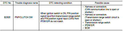
DTC DETECTION LOGIC
NOTE
:
• If DTC B2605 is displayed with DTC U1000, first perform the trouble diagnosis
for DTC U1000. Refer to
BCS-83, "DTC Logic".
• If DTC B2605 is displayed with DTC U1010, first perform the trouble diagnosis for DTC U1010. Refer to BCS-84, "DTC Logic".
DTC CONFIRMATION PROCEDURE
1.PERFORM DTC CONFIRMATION PROCEDURE
1. Shift the selector lever to the P position.
2. Turn ignition switch ON and wait 1 second or more.
3. Shift the selector lever to the N position and wait 1 second or more.
4. Shift the selector lever to any position other than P and N, and wait 1 second or more.
5. Check DTC in “Self Diagnostic Result” mode of “BCM” using CONSULT-III.
Is DTC detected? YES >> Go to SEC-90, "Diagnosis Procedure".
NO >> INSPECTION END
Diagnosis Procedure
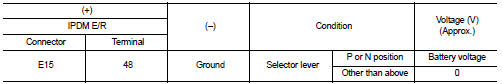
1.CHECK IPDM E/R INPUT SIGNAL
1. Turn ignition switch OFF.
2. Disconnect IPDM E/R connector.
3. Turn ignition switch ON.
4. Check voltage between IPDM E/R harness connector and ground.
Is the inspection result normal? YES >> GO TO 3.
NO >> GO TO 2.
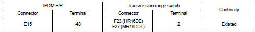
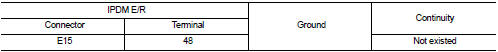
2.CHECK IPDM E/R INPUT SIGNAL CIRCUIT
1. Turn ignition switch OFF.
2. Disconnect transmission range switch connector.
3. Check continuity between IPDM E/R harness connector and BCM harness connector.
4. Check continuity between IPDM E/R harness connector and ground.
Is the inspection result normal? YES >> GO TO 6.
NO >> Repair or replace harness.
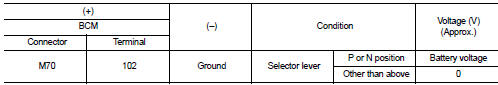
3.CHECK BCM INPUT SIGNAL
1. Turn ignition switch OFF.
2. Disconnect BCM connector.
3. Turn ignition switch ON.
4. Check voltage between BCM harness connector and ground.
Is the inspection result normal? YES >> GO TO 5.
NO >> GO TO 4.
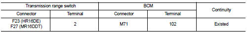
4.CHECK BCM INPUT SIGNAL CIRCUIT
1. Turn ignition switch OFF.
2. Disconnect transmission range switch connector.
3. Disconnect BCM connector.
4. Check continuity between transmission range switch harness connector and BCM harness connector.
5. Check continuity between CVT assembly harness connector and ground.
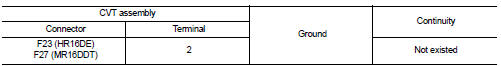
Is the inspection result normal? YES >> GO TO 6.
NO >> Repair or replace harness.
5.REPLACE BCM
1. Replace BCM. Refer to BCS-93, "Removal and Installation".
2. Perform initialization of BCM and registration of all Intelligent Keys using CONSULT-III.
For initialization and registration procedures, refer to CONSULT-III Operation Manual NATS-IVIS/NVIS.
3. Perform DTC CONFIRMATION PROCEDURE for DTC B2605. Refer to SEC-90, "DTC Logic".
Is DTC B2605 detected again? YES >> Replace IPDM E/R. Refer to PCS-34, "Removal and Installation".
NO >> INSPECTION END
6.CHECK INTERMITTENT INCIDENT
Refer to GI-42, "Intermittent Incident".
>> INSPECTION END
 B2604 shift position
DTC Logic
DTC DETECTION LOGIC
NOTE:
• If DTC B2604 is displayed with DTC U1000, first perform the trouble diagnosis
for DTC U1000. Refer to
BCS-83, "DTC Logic".
• If DTC B2604 is disp ...
 B2608 starter relay
DTC Logic
DTC DETECTION LOGIC
NOTE:
• If DTC B2608 is displayed with DTC U1000, first perform the trouble diagnosis
for DTC U1000. Refer to
BCS-83, "DTC Logic".
• If DTC B2608 is disp ...
Other materials:
General Precautions
• Turn ignition switch OFF and disconnect the battery cable
from the negative terminal before connecting or disconnecting
the CVT assembly harness connector. Because battery
voltage is applied to TCM even if ignition switch is turned
OFF.
• When connecting or disconnecting pin connectors into ...
P range interlock door lock/unlock function does not operate
Diagnosis Procedure
1.CHECK “AUTOMATIC LOCK/UNLOCK SELECT” SETTING IN “WORK SUPPORT”
1. Select “DOOR LOCK” of “BCM” using CONSULT-III.
2. Select “AUTOMATIC LOCK/UNLOCK SELECT” in “WORK SUPPORT” mode.
3. Check “AUTOMATIC LOCK/UNLOCK SELECT” setting in “WORK SUPPORT”.
Refer to DLK-501, "DO ...
Fuel level sensor unit, fuel filter and fuel pump assembly
Exploded View
1. Fuel tank
2. Rock ring
3.
Fuel level sensor unit, fuel filter and
fuel pump assembly
4. O-ring
: Vehicle front
: Always replace after every
disassembly.
: N·m (kg-m, ft-lb)
1. Fuel filter and fuel pump assembly
2. Fuel gauge
Removal and Installation
WARNING:
...
