Nissan Juke Service and Repair Manual : B2603 shift position
DTC Logic
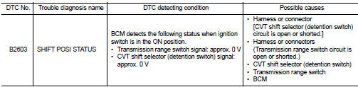
DTC DETECTION LOGIC
NOTE
:
• If DTC B2603 is displayed with DTC B2601, first perform the trouble diagnosis
for DTC B2601. Refer to
SEC-79, "DTC Logic".
DTC CONFIRMATION PROCEDURE
1.PERFORM DTC CONFIRMATION PROCEDURE 1
1. Shift the selector lever to the P position.
2. Turn ignition switch ON and wait 1 second or more.
3. Check DTC in “Self Diagnostic Result” mode of “BCM” using CONSULT-III.
Is DTC detected? YES >> Go to SEC-84, "Diagnosis Procedure".
NO >> GO TO 2.
2.PERFORM DTC CONFIRMATION PROCEDURE 2
1. Shift the selector lever to any position other than P, and wait 1 second or more.
2. Check DTC in “Self Diagnostic Result” mode of “BCM” using CONSULT-III.
Is DTC detected? YES >> Go to SEC-84, "Diagnosis Procedure".
NO >> INSPECTION END
Diagnosis Procedure
1.INSPECTION START
Perform inspection in accordance with procedure that confirms DTC.
Which procedure confirms DTC? DTC confirmation procedure 1>>GO TO 2.
DTC confirmation procedure 2>>GO TO 7.
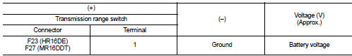
2.CHECK TRANSMISSION RANGE SWITCH POWER SUPPLY
1. Turn ignition switch OFF.
2. Disconnect transmission range switch connector.
3. Turn ignition switch ON.
4. Check voltage between transmission range switch harness connector and ground.
Is the inspection result normal?
YES >> GO TO 4.
NO-2 >> GO TO 3.
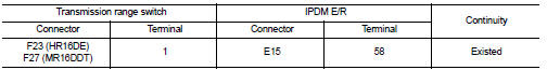
3.CHECK TRANSMISSION RANGE SWITCH POWER SUPPLY CIRCUIT
1. Turn ignition switch OFF.
2. Disconnect IPDM E/R connector.
3. Check continuity between transmission range switch harness connector and IPDM E/R harness connector.
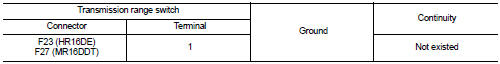
4. Check continuity between transmission range switch harness connector and ground.
Is the inspection result normal? YES >> Check 10 A fuse (No. 56, located in IPDM E/R).
NO >> Repair or replace harness.
4.CHECK BCM INPUT SIGNAL
1. Turn ignition switch OFF.
2. Connect transmission range switch harness connector.
3. Turn ignition switch ON.
4. Check voltage between BCM harness connector and ground.
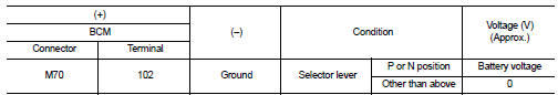
Is the inspection result normal? YES >> GO TO 11.
NO >> GO TO 5.
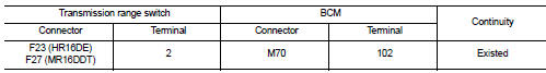
5.CHECK BCM INPUT SIGNAL CIRCUIT
1. Turn ignition switch OFF.
2. Disconnect transmission range switch connector.
3. Check continuity between transmission range switch harness connector and BCM harness connector.
4. Check continuity between transmission range switch harness connector and ground
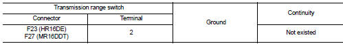
Is the inspection result normal?
YES >> GO TO 6.
NO >> Repair or replace harness.
6.CHECK TRANSMISSION RANGE SWITCH
Refer to SEC-87, "Component Inspection (Transmission Range Switch)".
Is the inspection result normal? YES >> GO TO 12.
NO >> Replace transmission range switch. Refer to TM-278, "Removal and Installation" (CVT: RE0F10B) or TM-508, "Removal and Installation" (CVT: RE0F11A).
7.CHECK CVT SHIFT SELECTOR POWER SUPPLY
1. Turn ignition switch OFF.
2. Disconnect CVT shift selector (detention switch) connector.
3. Check voltage between CVT shift selector (detention switch) harness connector and ground.
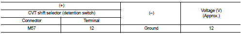
Is the inspection result normal? YES >> GO TO 9.
NO >> GO TO 8.
8.CHECK CVT SHIFT SELECTOR POWER SUPPLY CIRCUIT
1. Disconnect BCM connector.
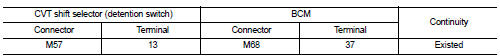
2. Check continuity between CVT shift selector (detention switch) harness connector and BCM harness connector.
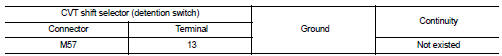
3. Check continuity between CVT shift selector (detention switch) harness connector and ground.
Is the inspection result normal? YES >> GO TO 11.
NO >> Repair or replace harness.
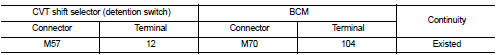
9.CHECK CVT SHIFT SELECTOR CIRCUIT
1. Disconnect BCM connector.
2. Check continuity between CVT shift selector (detention switch) harness connector and BCM harness connector.
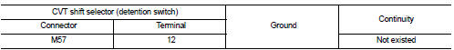
3. Check continuity between CVT shift selector (detention switch) harness connector and ground.
Is the inspection result normal?
YES >> GO TO 10.
NO >> Repair or replace harness.
10.CHECK CVT SHIFT SELECTOR (DETENTION SWITCH)
Refer to SEC-87, "Component Inspection [CVT Shift Selector (Detention Switch)]".
Is the inspection result normal? YES >> GO TO 12.
NO >> Replace CVT shift selector. Refer to TM-270, "Removal and Installation" (CVT: RE0F10B) or TM- 481, "Removal and Installation" (CVT: RE0F11A).
11.REPLACE BCM
1. Replace BCM. Refer to BCS-93, "Removal and Installation".
2. Perform initialization of BCM and registration of all Intelligent Keys using CONSULT-III.
For initialization and registration procedures, refer to CONSULT-III Operation Manual NATS-IVIS/NVIS.
>> INSPECTION END
12.CHECK INTERMITTENT INCIDENT
Refer to GI-42, "Intermittent Incident".
>> INSPECTION END
Component Inspection (Transmission Range Switch)
1.CHECK TRANSMISSION RANGE SWITCH
1. Turn ignition switch OFF.
2. Disconnect transmission range switch connector.
3. Check continuity between transmission range switch terminals.
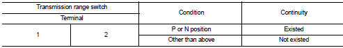
Is the inspection result normal? YES >> INSPECTION END
NO >> Replace transmission range switch. Refer to TM-278, "Removal and Installation" (CVT: RE0F10B) or TM-508, "Removal and Installation" (CVT: RE0F11A).
Component Inspection [CVT Shift Selector (Detention Switch)]
1.CHECK CVT SHIFT SELECTOR (DETENTION SWITCH)
1. Turn ignition switch OFF.
2. Disconnect CVT shift selector connector.
3. Check continuity between CVT shift selector (detention switch) terminals.
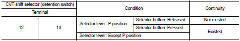
Is the inspection result normal? YES >> INSPECTION END
NO >> Replace CVT shift selector. Refer to TM-270, "Removal and Installation" (CVT: RE0F10B) or TM- 481, "Removal and Installation" (CVT: RE0F11A).
 B2602 shift position
DTC Logic
DTC DETECTION LOGIC
NOTE:
• If DTC B2602 is displayed with DTC U1000, first perform the trouble diagnosis
for DTC U1000. Refer to
BCS-83, "DTC Logic".
• If DTC B2602 is disp ...
 B2604 shift position
DTC Logic
DTC DETECTION LOGIC
NOTE:
• If DTC B2604 is displayed with DTC U1000, first perform the trouble diagnosis
for DTC U1000. Refer to
BCS-83, "DTC Logic".
• If DTC B2604 is disp ...
Other materials:
Power outlet
The power outlet is located in the instrument panel.
CAUTION
• The outlet and plug may be hot during or immediately after use.
• Do not use with accessories that exceed a 12 volt, 120W (10A) power draw. Do not
use double adapters or more than one electrical accessory.
• Use power outle ...
Headlights
Fog may temporarily form inside the lens of the exterior lights in the rain or
in a car wash. A temperature difference between the inside and the outside of the
lens causes the fog. This is not a malfunction. If large drops of water collect
inside the lens, contact a NISSAN dealer.
Replacing
...
Oil seal
Valve oil seal
VALVE OIL SEAL : Removal and Installation
REMOVAL
1. Remove camshafts. Refer to EM-191, "Exploded View".
2. Remove valve lifters. Refer to EM-191, "Exploded View".
3. Rotate crankshaft, and set piston whose valve oil seal is to be removed to
TDC. This will p ...
