Nissan Juke Service and Repair Manual : B2581, B2582 intake sensor
DTC Logic
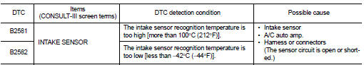
DTC DETECTION LOGIC
NOTE
:
• If DTC is displayed along with DTC U1000, first perform the trouble diagnosis
for DTC U1000. Refer to HAC-
51, "DTC Logic".
• If DTC is displayed along with DTC U1010, first perform the trouble diagnosis for DTC U1010. HAC-52, "DTC Logic".
DTC CONFIRMATION PROCEDURE
1.PERFORM DTC CONFIRMATION PROCEDURE
 With CONSULT-III
1. Turn ignition switch ON.
2. Select “Self Diagnostic Result” mode of “HVAC” using CONSULT-III.
3. Check DTC.
Is DTC detected? YES >> Refer to HAC-59, "Diagnosis Procedure".
NO >> INSPECTION END
Diagnosis Procedure
1.CHECK INTAKE SENSOR POWER SUPPLY
1. Turn ignition switch OFF.
2. Disconnect intake sensor connector.
3. Turn ignition switch ON.
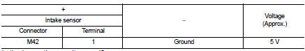
4. Check voltage between intake sensor harness connector and ground.
Is the inspection result normal? YES >> GO TO 2.
NO >> GO TO 4.
2.CHECK INTAKE SENSOR GROUND CIRCUIT FOR OPEN
1. Turn ignition switch OFF.
2. Disconnect A/C auto amp. connector.
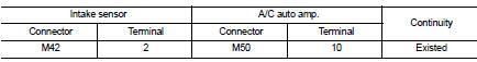
3. Check continuity between intake sensor harness connector and A/C auto amp harness connector.
Is the inspection result normal?
YES >> GO TO 3.
NO >> Repair harness or connector.
3.CHECK INTAKE SENSOR
Check intake sensor. Refer to HAC-57, "Component Inspection".
Is the inspection result normal? YES >> Replace A/C auto amp. Refer to HAC-91, "Removal and Installation".
NO >> Replace intake sensor. Refer to HAC-95, "Removal and Installation".
4.CHECK INTAKE SENSOR POWER SUPPLY CIRCUIT FOR OPEN
1. Turn ignition switch OFF.
2. Disconnect A/C auto amp. connector.
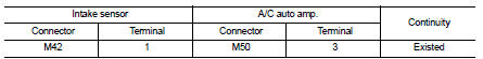
3. Check continuity between intake sensor harness connector and A/C auto amp. harness connector.
Is the inspection result normal? YES >> GO TO 5.
NO >> Repair harness or connector.
5.CHECK INTAKE SENSOR POWER SUPPLY CIRCUIT FOR SHORT
Check continuity between intake sensor harness connector and ground.
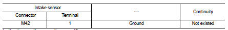
Is the inspection result normal? YES >> Replace A/C auto amp. Refer to HAC-91, "Removal and Installation".
NO >> Repair harness or connector.
Component Inspection
1.CHECK INTAKE SENSOR
1. Remove intake sensor. Refer to HAC-95, "Removal and Installation".
2. Check resistance between intake sensor terminals. Refer to applicable table for the normal value.
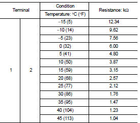
Is the inspection result normal? YES >> INSPECTION END
NO >> Replace intake sensor. Refer to HAC-95, "Removal and Installation".
 B257B, B257C ambient sensor
DTC Logic
DTC DETECTION LOGIC
NOTE:
• If DTC is displayed along with DTC U1000, first perform the trouble diagnosis
for DTC U1000. Refer to HAC-
51, "DTC Logic".
• If DTC is displayed ...
 B2630, B2631 sunload sensor
DTC Logic
DTC DETECTION LOGIC
NOTE:
• If DTC is displayed along with DTC U1000, first perform the trouble diagnosis
for DTC U1000. Refer to HAC-
51, "DTC Logic".
• If DTC is displayed ...
Other materials:
Oil pan
Exploded View
1. Transaxle assembly
2. Oil pan gasket
3. Magnet
4. Oil pan
5. Overflow tube
6. Drain plug gasket
7. Drain plug
8. Oil pan fitting bolt
: Always replace after every
disassembly.
: N·m (kg-m, ft-lb)
: N·m (kg-m, it-lb)
Removal and Installation
REMOVAL
1. Remove t ...
Buzzer (combination meter)
Component Function Check
1.CHECK FUNCTION
1. Select “INTELLIGENT KEY” of “BCM” using CONSULT-III.
2. Select “INSIDE BUZZER” in “ACTIVE TEST” mode.
3. Check that the function operates normally according to the following
conditions.
Is the inspection result normal?
Yes >> Buzzer (combi ...
Microphone signal circuit
Description
Power is supplied from audio unit to microphone. The microphone transmits the
sound voice to the audio unit.
Diagnosis Procedure
1.CHECK CONTINUITY BETWEEN AUDIO UNIT AND MICROPHONE CIRCUIT
1. Turn ignition switch OFF.
2. Disconnect audio unit connector and microphone connector.
...
