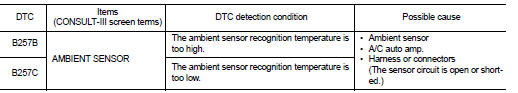
Nissan Juke Service and Repair Manual : B257B, B257C ambient sensor
DTC Logic
DTC DETECTION LOGIC
NOTE
:
• If DTC is displayed along with DTC U1000, first perform the trouble diagnosis
for DTC U1000. Refer to HAC-
141, "DTC Logic".
• If DTC is displayed along with DTC U1010, first perform the trouble diagnosis for DTC U1010. HAC-142, "DTC Logic".
DTC CONFIRMATION PROCEDURE
1.PERFORM DTC CONFIRMATION PROCEDURE
 With CONSULT-III
1. Turn ignition switch ON.
2. Select “Self Diagnostic Result” mode of “HVAC” using CONSULT-III.
3. Check DTC.
Is DTC detected? YES >> Refer to HAC-146, "Diagnosis Procedure".
NO >> INSPECTION END
Diagnosis Procedure
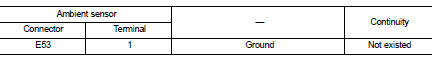
1.CHECK AMBIENT SENSOR POWER SUPPLY
1. Turn ignition switch OFF.
2. Disconnect ambient sensor connector.
3. Turn ignition switch ON.
4. Check voltage between ambient sensor harness connector and ground.
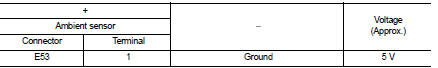
Is the inspection result normal? YES >> GO TO 2.
NO >> GO TO 4. 2.CHECK AMBIENT SENSOR GROUND CIRCUIT FOR OPEN
1. Turn ignition switch OFF.
2. Disconnect A/C auto amp. connector.
3. Check continuity between ambient sensor harness connector and A/C auto amp harness connector.
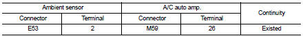
Is the inspection result normal?
YES >> GO TO 3.
NO >> Repair harness or connector.
3.CHECK AMBIENT SENSOR
Check ambient sensor. Refer to HAC-147, "Component Inspection".
Is the inspection result normal? YES >> Replace A/C auto amp. Refer to HAC-188, "Removal and Installation".
NO >> Replace ambient sensor. Refer to HAC-189, "Removal and Installation".
4.CHECK AMBIENT SENSOR POWER SUPPLY CIRCUIT FOR OPEN
1. Turn ignition switch OFF.
2. Disconnect A/C auto amp. connector.
3. Check continuity between ambient sensor harness connector and A/C auto amp. harness connector.
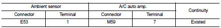
Is the inspection result normal? YES >> GO TO 5.
NO >> Repair harness or connector.
5.CHECK AMBIENT SENSOR POWER SUPPLY CIRCUIT FOR SHORT
Check continuity between ambient sensor harness connector and ground.
Is the inspection result normal? YES >> Replace A/C auto amp. Refer to HAC-188, "Removal and Installation".
NO >> Repair harness or connector.
Component Inspection
1.CHECK AMBIENT SENSOR
1. Remove ambient sensor. Refer to HAC-189, "Removal and Installation".
2. Check resistance between ambient sensor terminals. Refer to applicable table for the normal value.
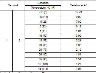
Is the inspection result normal? YES >> INSPECTION END
NO >> Replace ambient sensor. Refer to HAC-189, "Removal and Installation".
 B2578, B2579 In-vehicle sensor
DTC Logic
DTC DETECTION LOGIC
NOTE:
• If DTC is displayed along with DTC U1000, first perform the trouble diagnosis
for DTC U1000. Refer to HAC-
141, "DTC Logic".
• If DTC is displaye ...
 B2581, B2582 intake sensor
DTC Logic
DTC DETECTION LOGIC
NOTE:
• If DTC is displayed along with DTC U1000, first perform the trouble diagnosis
for DTC U1000. Refer to HAC-
141, "DTC Logic".
• If DTC is displaye ...
Other materials:
Loading tips
• The GVW must not exceed GVWR or GAWR as specified on the F.M.V.S.S./
C.M.V.S.S. certification label.
• Do not load the front and rear axle to the GAWR. Doing so will exceed the GVWR.
WARNING
• Properly secure all cargo with ropes or straps to help prevent it
from sliding or shif ...
Power supply and ground circuit
Diagnosis Procedure
1.CHECK ABS ACTUATOR AND ELECTRIC UNIT (CONTROL UNIT) IGNITION POWER
SUPPLY
1. Turn the ignition switch OFF.
2. Disconnect ABS actuator and electric unit (control unit) harness connector.
3. Check voltage between ABS actuator and electric unit (control unit) harness
conne ...
Main line betweeN DLC and MDU circuit
Diagnosis Procedure
1.CHECK HARNESS CONTINUITY (OPEN CIRCUIT)
1. Turn the ignition switch OFF.
2. Disconnect the battery cable from the negative terminal.
3. Disconnect the following harness connectors.
- ECM
- Multi display unit
4. Check the continuity between the data link connector and the ...
