Nissan Juke Service and Repair Manual : B2556 Push-button ignition switch
DTC Logic
DTC DETECTION LOGIC
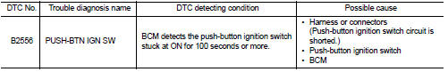
DTC CONFIRMATION PROCEDURE
1.PERFORM DTC CONFIRMATION PROCEDURE
1. Press push-button ignition switch under the following condition.
- Brake pedal: Not depressed 2. Release push-button ignition switch and wait 100 seconds or more.
3. Check DTC in “Self Diagnostic Result” mode of “BCM” using CONSULT-III.
Is DTC detected? YES >> Go to SEC-76, "Diagnosis Procedure".
NO >> INSPECTION END
Diagnosis Procedure
1.CHECK PUSH-BUTTON IGNITION SWITCH INPUT SIGNAL
1. Turn ignition switch OFF.
2. Disconnect push-button ignition switch connector.
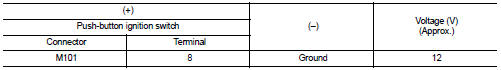
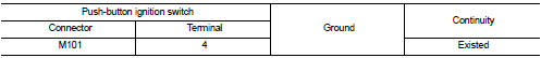
3. Check voltage between push-button ignition switch harness connector and ground.
Is the inspection result normal? YES >> GO TO 4.
NO >> GO TO 2.
2.CHECK PUSH-BUTTON IGNITION SWITCH CIRCUIT
1. Disconnect BCM connector and IPDM E/R connector.
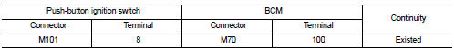
2. Check continuity between push-button ignition switch harness connector and BCM harness connector.
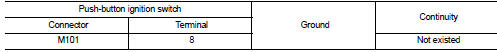
3. Check continuity between push-button ignition switch harness connector and ground.
Is the inspection result normal? YES >> GO TO 3.
NO >> Repair or replace harness.
3.REPLACE BCM
1. Replace BCM. Refer to BCS-93, "Removal and Installation".
2. Perform initialization of BCM and registration of all Intelligent Keys using CONSULT-III.
For initialization and registration procedures, refer to CONSULT-III Operation Manual NATS-IVIS/NVIS.
>> INSPECTION END
4.CHECK PUSH-BUTTON IGNITION SWITCH GROUND CIRCUIT
Check continuity between push-button ignition switch harness connector and ground.
Is the inspection result normal? YES >> GO TO 5.
NO >> Repair or replace harness.
5.CHECK PUSH-BUTTON IGNITION SWITCH
Refer to SEC-77, "Component Inspection".
Is the inspection result normal? YES >> GO TO 6.
NO >> Replace push-button ignition switch. Refer to SEC-168, "Removal and Installation".
6.CHECK INTERMITTENT INCIDENT
Refer to GI-42, "Intermittent Incident".
>> INSPECTION END
Component Inspection
1.CHECK PUSH-BUTTON IGNITION SWITCH
1. Turn ignition switch OFF.
2. Disconnect push-button ignition switch connector.
3. Check continuity between push-button ignition switch terminals.
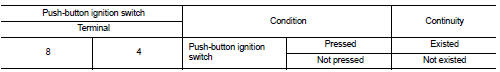
Is the inspection result normal? YES >> INSPECTION END
NO >> Replace push-button ignition switch. Refer to SEC-168, "Removal and Installation".
 B2555 stop lamp
DTC Logic
DTC DETECTION LOGIC
DTC CONFIRMATION PROCEDURE
1.PERFORM DTC CONFIRMATION PROCEDURE
1. Depress the brake pedal and wait 1 second or more.
2. Check DTC in “Self Diagnostic Result” mode ...
 B2557 vehicle speed
DTC Logic
DTC DETECTION LOGIC
NOTE:
• If DTC B2557 is displayed with DTC U1000, first perform the trouble diagnosis
for DTC U1000. Refer to
BCS-83, "DTC Logic".
• If DTC B2557 is disp ...
Other materials:
DTC/Circuit diagnosis
POSITION SWITCH
BACK-UP LAMP SWITCH : Component Inspection
1.CHECK BACK-UP LAMP SWITCH
1. Disconnect position switch connector. Refer to TM-24, "Removal and
Installation".
2. Check continuity between position switch terminals.
Is the inspection result normal?
YES >> INSPE ...
Removal and Installation Procedure for CVT Unit Connector
REMOVAL
• Rotate bayonet ring (A) counterclockwise. Pull out CVT unit harness
connector (B) upward and remove it.
INSTALLATION
1. Align marking (A) on CVT unit harness connector terminal with
marking (B) on bayonet ring. Insert CVT unit harness connector.
2. Rotate bayonet ring clockwise.
...
Basic inspection
DIAGNOSIS AND REPAIR WORK FLOW
Work Flow
OVERALL SEQUENCE
DETAILED FLOW
1.GET INFORMATION FOR SYMPTOM
1. Get detailed information from the customer about the symptom (the
condition and the environment when
the incident/malfunction occurred).
2. Check operation condition of the function th ...
